
Since its inception in 1958, lost foam casting has evolved from a novel invention into a mature production process for ferrous and non-ferrous alloys globally. My experience in foundry process design and commissioning has consistently shown that while the principle is elegant—replacing a vaporized foam pattern with molten metal—the practical execution, especially for steel castings, is fraught with specific challenges. The transition from single, large castings to high-volume, small-part production lines marks a significant industrial achievement, yet the intrinsic characteristics of the process introduce unique defect mechanisms not commonly encountered in traditional green sand or investment casting. The core of mastering lost foam casting lies in a deep, systematic understanding of the interactions between the foam pattern, the coating, the unbonded sand, and the dynamics of the molten metal. This article synthesizes my first-hand observations and analyses on the prevalent defects in steel lost foam casting, offering a detailed exploration of their root causes and comprehensive, practical strategies for their mitigation.
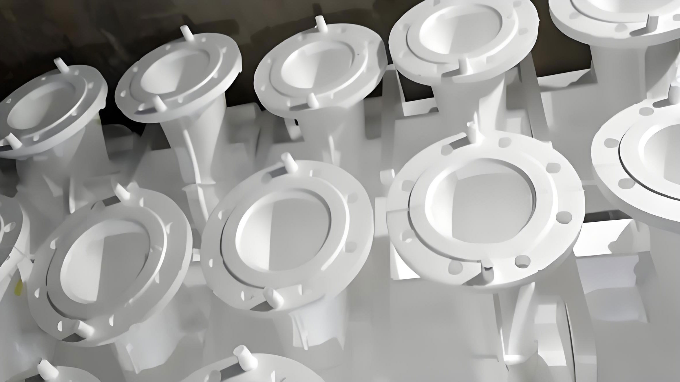
The fundamental process of lost foam casting involves several critical, interacting stages. A foam pattern, typically made from expandable polystyrene (EPS) or similar polymer, is fabricated and assembled. It is then coated with a refractory slurry and dried. This coated cluster is placed in a flask and surrounded by unbonded, dry sand, which is compacted via vibration. During pouring, molten metal immediately vaporizes the foam pattern, advancing through the cavity it leaves behind. The success of this operation hinges on perfect synchronization: the gasification products of the foam must be evacuated through the coating and sand faster than the metal fills the cavity, and the integrity of the mold cavity must be maintained against the thermal and mechanical shock. When this balance is disrupted, defects arise. For steel castings, the high pouring temperatures exacerbate these interactions, making defect prevention paramount.
1. Carbon Pick-Up: The Signature Challenge of Lost Foam Casting
Carbon pick-up is arguably the most distinctive and persistent defect in steel lost foam casting. It manifests as an unacceptable increase in the carbon content at the surface and sub-surface layers of the cast component, often leading to compromised machinability, altered mechanical properties, and potential failure in heat treatment. The defect originates from the fundamental chemistry of the process. The foam pattern, composed primarily of carbon and hydrogen (for EPS, approximating $$C_nH_{2n}$$), undergoes rapid thermal degradation upon contact with the molten steel. This degradation is not a simple gasification but a complex pyrolysis producing a mixture of gaseous, liquid, and solid phases.
The mechanism can be described in stages. Initially, the intense heat cracks the polymer chains. The hydrogen, having a higher affinity for oxygen than carbon, preferentially reacts with any available oxygen (from air trapped in the sand or coating) to form water vapor. Meanwhile, the carbon is liberated as free carbon (soot or lustrous carbon) and heavier hydrocarbon tars. In the confined space between the advancing metal front and the coating, these carbon-rich products can dissolve into or react with the surface layer of the steel, leading to carburization. The severity is influenced by multiple factors which can be framed in a kinetic relationship for carbon transfer:
$$ \frac{d[C]}{dt} = k \cdot A \cdot (C_{\text{potential}} – [C]_{\text{steel}}) $$
Where:
• $$ \frac{d[C]}{dt} $$ is the rate of carbon increase in the steel surface.
• $$ k $$ is a rate constant dependent on temperature and interfacial conditions.
• $$ A $$ is the effective contact area between the steel and pyrolytic products.
• $$ C_{\text{potential}} $$ is the carbon potential in the pyrolysis zone, related to foam density and composition.
• $$ [C]_{\text{steel}} $$ is the instantaneous carbon content at the steel surface.
Empirical observations from production consistently reveal a spatial pattern: carbon pick-up is minimal near the ingates, where fresh, hot metal first enters, and becomes progressively more severe towards the furthest points and top surfaces of the casting. This gradient occurs because the initial metal thermally “cleans” the cavity, but as it flows further, it cools slightly and becomes saturated with carbon from the continuing pyrolysis ahead of it. The last metal to fill remote sections and risers is the most contaminated. Based on this understanding, a multi-pronged control strategy is essential.
| Control Area | Specific Action | Mechanism & Rationale |
|---|---|---|
| Raw Material | Use low-density, high molecular weight EPS or specialized STMMA (copolymer). | Reduces total mass of carbon per pattern. STMMA generates less soot due to oxygen in its chain. |
| Control foam density tightly (e.g., 0.018-0.022 g/cm³). | Minimizes the absolute amount of carbonaceous material to be decomposed. | |
| Process Parameters | Optimize pouring temperature. | Higher temperatures accelerate foam gasification to gaseous products, reducing liquid/solid residue. However, too high can erode coating. |
| Employ adequate and controlled vacuum. | Enhances removal of pyrolysis gases before they interact with metal. Typical range: 0.045-0.055 MPa for steel. | |
| Maximize coating and sand permeability. | Facilitates rapid evacuation of decomposition gases, lowering partial pressure of carbon species at the metal interface. | |
| Use “anti-carburizing” coatings. | Contains oxidizing agents (e.g., iron oxide) that help gasify carbon to CO/CO2 before it contacts the steel. | |
| Gating & Risering Design | Place feeder heads/risers at the furthest points from ingates. | Exploits the carbon gradient. The most carbon-rich metal is diverted into the riser, which is later removed, leaving cleaner metal in the casting body. |
2. Gas-Related Defects: Porosity in Lost Foam Casting
Porosity remains a critical quality concern in lost foam casting, but its sources are more varied than in conventional processes. Correct diagnosis is essential, as the prevention strategy differs radically based on the pore’s origin. We can classify porosity into distinct categories.
2.1 Pyrolysis Gas Entrapment Porosity: This is a direct consequence of the foam decomposition process. If the metal front becomes turbulent or wraps around a section of foam, trapping it, the gas generated from the pyrolysis of that isolated foam volume has no escape path and forms a large, often spherical pore. The interior surface of such pores is typically coated with a black, shiny carbon film. Prevention focuses on ensuring a laminar, progressive fill and efficient gas evacuation. The key parameters are pouring velocity, gating design, and vacuum level. The condition for avoiding gas entrapment can be modeled by comparing the gas generation rate to the evacuation rate:
$$ Q_{\text{gas, gen}}(t) = \rho_{\text{foam}} \cdot V_{\text{pyro}}(t) \cdot R(T) $$
$$ Q_{\text{gas, evac}}(t) = \frac{k_{\text{coat}} \cdot A_{\text{coat}} \cdot (P_{\text{int}} – P_{\text{vac}})}{\mu \cdot L_{\text{coat}}} $$
To prevent entrapment: $$ Q_{\text{gas, evac}}(t) \geq Q_{\text{gas, gen}}(t) $$ throughout the pour.
Where $$R(T)$$ is the temperature-dependent gasification rate, $$k_{\text{coat}}$$ is coating permeability, and $$P_{\text{int}}$$ is the interfacial pressure.
2.2 Moisture and Volatile-Related Porosity: This stems from inadequate drying of the foam pattern (retained pentane blowing agent) or the water-based refractory coating. Upon pouring, the rapid vaporization of this moisture/volatile creates high local gas pressure, forcing bubbles into the solidifying metal. These pores are often smaller and more numerous than pyrolysis pores. The remedy is strict process control: sufficient air-drying time for patterns after molding and a definitive, controlled drying cycle for the coating (often using forced hot air or low-temperature ovens).
2.3 Air Aspiration Porosity: This is a classic gating system defect. If the sprue is not kept full during pouring, a funnel vortex can form, sucking air into the metal stream. This air is then carried into the mold cavity. In lost foam casting, this is combated by using a pouring cup that maintains a constant metal head, employing tapered sprues, and sometimes using hollow sprue patterns to reduce the gas load from burning foam in the sprue itself.
2.4 Metallurgical Porosity: This originates from the steel melt itself—due to inadequate deoxidation (leaving dissolved oxygen which forms CO pores during solidification) or high hydrogen/nitrogen content. This underscores that lost foam casting does not bypass standard metallurgical best practices; in fact, it demands even cleaner metal due to the reactive environment. Effective ladle treatment, deoxidation with Al, Si, or Ca, and proper slag control are non-negotiable.
| Porosity Type | Key Identifying Features | Primary Causes | Corrective Measures |
|---|---|---|---|
| Pyrolysis Gas Entrapment | Large, rounded pores; shiny black carbon lining. | Turbulent fill; trapped foam; low permeability/ vacuum. | Design for laminar fill. Increase coating/sand permeability. Optimize vacuum level and pouring speed. |
| Moisture/Volatile | Clusters of smaller pores; may be subsurface. | Wet coating; undried foam (excess pentane). | Implement strict coating drying schedule. Control foam aging and drying. |
| Air Aspiration | Elongated or spherical pores near gates or in upper sections. | Unfilled sprue; vortexing in pouring cup. | Use pressurized gating; maintain pouring basin head. Consider hollow sprue patterns. |
| Metallurgical (e.g., CO, H2) | Small, often interdendritic pores; distributed widely. | Poor deoxidation; high gas content in melt. | Rigorous melt deoxidation and degassing. Use clean, dry charge materials. |
3. Inclusions and Sand Penetration: The Battle for Cavity Integrity
Inclusions—non-metallic materials embedded in the casting—are a major source of scrap in lost foam casting. They are classified as either internal sand inclusions (sand grains) or slag/coating inclusions (agglomerated pyrolysis residues and refractory bits). The defect often becomes visible only after machining, appearing as hard, white (silica) or dark (carbonaceous/refractory) spots. The root cause is the breach of the fragile refractory coating, the only barrier between the flowing metal and the loose sand mold.
The failure mechanism is often a combination of thermal shock and mechanical erosion. When hot metal first enters the sprue, it can cause local coating spalling if the coating lacks sufficient hot strength. The unbonded sand then flows into this breach, akin to a miniature sand slide, and is carried into the casting. Similarly, if the coating cracks due to poor dry strength or improper handling, sand ingress occurs. The high fluidity of the steel and the vacuum assist further contribute to this sand “bulk flow” phenomenon. Preventing this is a systems engineering challenge, involving every step from coating selection to pouring.
3.1 The Paramount Role of the Coating: The coating is the linchpin. For steel lost foam casting, its requirements are extreme:
• High Dry Strength: To resist cracking during pattern handling, transportation, and sand filling/vibration.
• High Hot Strength and Erosion Resistance: To withstand the thermal shock and mechanical冲刷 of the molten steel without spalling or eroding.
• Excellent Permeability: To allow rapid gas escape, preventing back-pressure and gas-driven metal turbulence that can erode the coating.
• Good Adherence and Uniformity: A pinhole or thin spot is a potential failure point.
Formulations often include high-refractoriness ingredients like fused silica, zircon, or aluminosilicates, bound by sophisticated inorganic and organic binder systems.
3.2 Process Discipline: Even the best coating can be defeated by poor practice.
• Molding/Sanding: The pattern must be placed gently on the base sand. Sand should be added initially with soft, manual placement around delicate features before starting vibration, to avoid impact damage. Vibration parameters (frequency, amplitude, time) must be optimized to compact sand without fracturing the coating.
• Gating System Sealing: The joint between the pouring cup, sprue, and pattern cluster must be meticulously sealed with a high-strength paste or tape to prevent sand from trickling down at the start of the pour.
• Pouring Practice: Use the smallest feasible ladle to minimize pour height and metal impact. The pour should be rapid enough to maintain a positive metal head but controlled to avoid excessive冲刷. Pouring temperature is a critical trade-off: too low increases mistuns and carbon defects; too high increases erosion and chemical attack on the coating.
3.3 System Design for Inclusion Control: The gating system itself can be an inclusion trap. Incorporating a slag trap or a filter in the runner can capture loose sand or agglomerated pyrolysis residues before they enter the casting cavity. Furthermore, strategic placement of blind risers or “dirt traps” at the end of runners or in non-critical areas of the casting can collect contaminated initial metal flow.
4. Back-Spray (Reverse Ejection) and Process Stability
Back-spray is a dramatic and hazardous defect where metal is ejected from the mold during pouring, often accompanied by flames. It is a clear symptom of a severe pressure imbalance within the mold cavity. The cause is a mismatch where the rate of gas generation from the foam pyrolysis exceeds the rate at which the vacuum system and permeable coating can evacuate it. The internal pressure $$P_{\text{int}}$$ rises until it exceeds the metallostatic pressure $$ \rho g h $$ at the pouring point, resulting in an explosive reversal of flow.
The condition for stability can be expressed as:
$$ P_{\text{int}}(t) = P_{\text{vac}} + \frac{Q_{\text{gas, gen}}(t) \cdot \mu \cdot L_{\text{coat}}}{k_{\text{coat}} \cdot A_{\text{coat}}} < \rho g h(t) + P_{\text{atm}} $$
Preventing back-spray involves reducing the left side of the inequality and/or increasing the right side:
• Reduce Gas Generation (Qgas, gen): Use low-density foam; ensure patterns and coatings are thoroughly dry; apply controlled, adequate vacuum to promote pyrolysis in an oxygen-depleted atmosphere (reducing flaming, which generates gas faster).
• Increase Gas Evacuation: Use coatings with high permeability; ensure the sand has uniform, adequate grain size and no fines to maintain overall mold permeability.
• Increase Metallostatic Head (ρgh): Design the gating to ensure a tall enough sprue is quickly filled; pour quickly and consistently at the start to establish the metal head pressure. A well-designed pouring basin that keeps the sprue full is critical.
5. A Holistic Framework for Quality in Lost Foam Casting
The journey to producing sound steel castings via lost foam casting is one of integrated system control. It is insufficient to excel in only one area, such as having a perfect foam pattern, if the coating is weak or the pouring practice is poor. Each defect interrelates with multiple process variables. For instance, increasing pouring temperature might help reduce carbon pick-up and mistuns but can increase sand penetration and erosion. Increasing vacuum improves cavity integrity and gas removal but can increase porosity from turbulence if not balanced with gating design.
Therefore, successful implementation requires a disciplined, data-driven approach:
1. Material Specification and Control: Rigorously control foam type, density, and bonding. Select and qualify coatings based on comprehensive testing (permeability, strength, refractoriness).
2. Process Parameter Optimization and Monitoring: Establish and document optimal windows for key parameters. This includes defining precise drying cycles for patterns and coatings, standardizing vibration and sand-filling procedures, and setting controlled limits for pouring temperature, pouring time, and vacuum level.
3. Robust Gating and Risering Design: Utilize simulation software to predict fill patterns, solidification, and thermal gradients. Design gating for laminar, progressive filling from the bottom-up where possible, and place feeders to sequester contaminated metal.
4. Melt Quality as a Foundation: Never compromise on steelmaking practice. The melt must be properly refined, deoxidized, and at the correct temperature and chemistry before it ever touches the foam pattern.
5. Continuous Improvement Loop: Systematically log all process parameters for each mold poured and correlate them with final casting inspection (NDT, machining) results. Use this data to continually refine the process windows.
| Process Parameter | Primary Positive Effect | Potential Negative Effect if Excessive/Incorrect | Typical Target for Steel Castings |
|---|---|---|---|
| Pouring Temperature | Improves fluidity, reduces mistuns, promotes foam gasification. | Increases erosion/cracking of coating; worsens metal-mold reaction; can increase grain size. | Material-dependent, often 50-100°C above alloy liquidus. |
| Vacuum Level | Improves mold rigidity, enhances gas evacuation, reduces pyrolysis time. | Can cause turbulent fill & gas entrapment; may increase sand penetration if coating fails. | 0.045 – 0.065 MPa (depending on casting size and geometry). |
| Coating Permeability | Allows rapid gas escape, reduces back-pressure and porosity risk. | If too high, can allow metal penetration (burn-on); may reduce coating strength. | Must be balanced with thickness and strength; determined experimentally. |
| Pouring Speed | Ensures positive metal head, reduces mistuns. | Causes turbulence, gas entrapment, and coating erosion. | Fast initial fill of sprue, then controlled to maintain sprue head. |
| Pattern Density | Higher density improves pattern strength and surface finish. | Massively increases gas load and carbon potential. | As low as possible (0.018-0.024 g/cm³) while maintaining handling strength. |
In conclusion, lost foam casting for steel is a process of immense potential, offering benefits in design flexibility, reduced machining, and sand handling. However, its unique defect palette demands a profound and respectful understanding of the underlying physics and chemistry. By treating the process as a closely coupled system—where foam, coating, sand, vacuum, and molten metal are all active, interdependent participants—foundries can move from battling defects to reliably producing high-integrity castings. The path to mastery is paved with meticulous control, systematic analysis, and an unwavering commitment to each detail in the chain of production. The future of lost foam casting for steel lies not in seeking a single silver bullet, but in the rigorous, holistic optimization of this fascinating and complex manufacturing symphony.