
In my recent work, I focused on the design and optimization of a sand casting process for a critical automotive part, specifically a cushion block used in transmission systems. This sand casting part is essential for vibration damping and must withstand cyclic mechanical loads, requiring high integrity without defects like shrinkage porosity, cold shuts, or cracks. My goal was to develop a robust sand casting process that ensures quality and efficiency, leveraging numerical simulation for validation and improvement. Sand casting parts like this are common in automotive applications due to their cost-effectiveness and ability to produce complex geometries. Throughout this article, I will detail my approach, emphasizing the iterative design and simulation phases that led to a successful outcome.
The cushion block is a plate-like sand casting part with dimensions of 259 mm × 179 mm × 102 mm, a net weight of 7.4 kg, and an average wall thickness of 8.8 mm. Its structure includes multiple ribs, holes, and two cylindrical cavities, which necessitate careful sand core design. For material selection, I chose QT450-10 ductile iron, as it offers good strength and ductility for automotive sand casting parts. The chemical composition requirements for QT450-10 are critical for achieving the desired properties, and I used a cupola-induction furnace duplex melting process. Below is a table summarizing the chemical composition range used in my work:
| Element | Composition Range (wt.%) |
|---|---|
| C | 3.70–4.00 |
| Si | 2.15–2.93 |
| Mn | 0.46–0.66 |
| P | 0.027–0.035 |
| S | 0.010–0.016 |
| Mg | 0.027–0.050 |
| RE | 0.026–0.043 |
In sand casting parts, the minimum wall thickness is vital to prevent defects. For this ductile iron sand casting part, the minimum wall thickness requirement is 4–8 mm, and my design had a minimum of 8 mm, ensuring adequate fluidity. The ribs, all 8 mm thick, were analyzed for structural integrity; they enhance stiffness without causing hot spots. My initial process involved manual molding and core-making using self-setting furan resin sand, as machine molding was unsuitable for the complex internal features of this sand casting part. The sand casting process was planned for two parts per mold to optimize production.
For the casting process design, I selected the parting plane and pouring position to minimize defects. After evaluating several schemes, I opted for a bottom gating system with the critical bottom planes placed downward. This reduces turbulence and oxidation, common issues in sand casting parts. The gating system was designed as a bottom-pouring lap type with a sprue, runner, and ingates. To calculate the gating dimensions, I used fluid dynamics principles. For instance, the flow rate Q can be expressed as: $$ Q = A \cdot v $$ where A is the cross-sectional area and v is the velocity. The velocity v depends on the head height h, given by Torricelli’s law: $$ v = \sqrt{2gh} $$ where g is gravitational acceleration. In sand casting parts, ensuring laminar flow is key, so I designed a trapezoidal runner and flat ingates. A filter with 2.5 mm × 2.5 mm mesh was included to trap slag.
Process parameters were set based on standards for sand casting parts. The machining allowances varied by surface: 1.5 mm for the bottom faces, 0.5 mm for sides, and 2 mm for top faces, corresponding to CT11 tolerance grade. The pattern shrinkage allowance was 0.8% for ductile iron, and a draft angle of 0°35′ was applied to facilitate pattern removal. These parameters are summarized in the table below:
| Parameter | Value |
|---|---|
| Machining Allowance (Face A) | 1.5 mm |
| Machining Allowance (Face B) | 1.5 mm |
| Machining Allowance (Face C) | 0.5 mm |
| Machining Allowance (Face D) | 2.0 mm |
| Shrinkage Allowance | 0.8% |
| Draft Angle | 0°35′ |
The sand core design was intricate due to the complex geometry of this sand casting part. I split the core into five pieces to simplify manufacturing and ensure accuracy. Cores #1, #2, and #3 were placed horizontally, while #4 and #5 were vertically positioned with interlocking features to prevent misalignment. Venting was incorporated on all cores to release gases during pouring, a common necessity in sand casting parts to avoid blowholes. Core prints and locators were used to secure cores in the mold. The cores were made from furan resin sand without chills, as their volume was below 0.05 m³. This modular core approach is beneficial for producing precise sand casting parts with internal cavities.
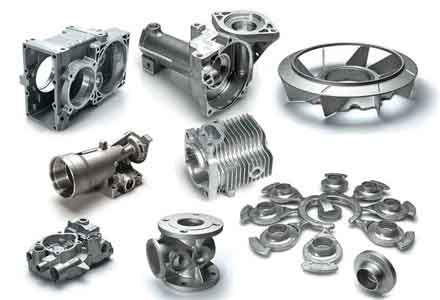
I employed AnyCasting software for numerical simulation to analyze and optimize the sand casting process. The pre-processing involved meshing the 3D model and setting boundary conditions. The pouring temperature was 1,350°C, and the heat transfer coefficients were defined: 0.001 W/(m²·℃) for air and 0.1 W/(m²·℃) for mold-sand interfaces. The simulation captured filling and solidification sequences. The filling time was 4.01 seconds, with stable flow and no major turbulence, as shown by temperature gradients. For solidification, I observed that the outer regions cooled first, leading to potential shrinkage in internal hot spots. The solidification time t can be estimated using Chvorinov’s rule: $$ t = B \left( \frac{V}{A} \right)^2 $$ where V is volume, A is surface area, and B is a mold constant. For this sand casting part, the modulus (V/A) varied, causing differential cooling.
The initial simulation revealed defects, with a probabilistic defect parameter indicating 0.18% volume of residual melt. To address this, I designed a feeding system with nine risers placed on the top cylindrical bosses to promote directional solidification. Additionally, eight chills were arranged in circular patterns at thick sections to accelerate cooling. The riser design considered the required feed metal volume, calculated as: $$ V_{\text{riser}} = \frac{V_{\text{casting}} \cdot \alpha}{\beta} $$ where α is the shrinkage percentage (about 5% for ductile iron) and β is the riser efficiency. Venting was added at the top to exhaust gases. After optimization, the defect volume reduced to 0.09%, and the casting yield exceeded 90%. The table below compares key metrics before and after optimization:
| Metric | Initial Design | Optimized Design |
|---|---|---|
| Filling Time | 4.01 s | 4.01 s (stable) |
| Defect Volume Fraction | 0.18% | 0.09% |
| Casting Yield | ~85% | >90% |
| Solidification Sequence | Random | Directional |
The optimized process demonstrated sequential solidification, with risers and chills effectively controlling thermal gradients. This is crucial for sand casting parts to minimize internal defects. I validated the process by producing actual castings, which met all quality requirements with high dimensional accuracy. The use of simulation tools like AnyCasting allowed me to iterate designs virtually, saving time and material. For sand casting parts, such simulations are invaluable for predicting flow patterns and defect formation. The final sand casting part exhibited no visible defects, confirming the effectiveness of my design approach.
In conclusion, my work on this automotive sand casting part highlights the importance of integrated design and simulation in modern sand casting. By carefully selecting process parameters, designing modular sand cores, and using numerical optimization, I achieved a reliable process for high-quality sand casting parts. The key takeaways include the benefits of bottom gating for complex sand casting parts, the role of risers and chills in controlling solidification, and the value of simulation in reducing trial-and-error. Future work could explore other alloys or larger production scales for similar sand casting parts. Overall, this project underscores how advanced techniques can enhance traditional sand casting for demanding automotive applications.