
Drawing upon extensive experience in the production of critical components like compressor cylinders, I have dedicated significant effort to understanding and solving the unique defect challenges presented by permanent mold (metal mold) casting of cast iron. While sand casting defect analysis provides a foundational understanding of common issues like porosity and inclusions, the transition to metal molds introduces a distinct set of physical constraints that exacerbate certain flaws and create entirely new ones. The high thermal conductivity, lack of permeability, and fast solidification rates of metal molds shift the defect formation paradigm. This article synthesizes practical insights into the root causes of prevalent defects in iron cylinder castings and outlines effective mitigation strategies, often contrasting them with approaches used for sand casting defect control.
The fundamental characteristics of the metal mold process create a unique environment. Unlike sand molds, metal molds have negligible gas permeability, forcing all gases generated or entrapped during pouring to either dissolve in the metal or escape through specifically designed vents. Their high thermal conductivity and heat capacity lead to rapid solidification, which is beneficial for achieving fine microstructures like Type D graphite but also increases the risk of mistruns and shrinkage-related issues if not managed. Furthermore, the fast cooling can trap impurities that might otherwise have time to float out in a slower-cooling sand mold. Therefore, a sand casting defect prevention plan is insufficient; the process requires its own specialized focus.
| Process Characteristic | Sand Casting | Metal Mold Casting | Impact on Defect Formation |
|---|---|---|---|
| Mold Permeability | High | Negligible | Greatly increases risk of gas entrapment and blowholes. |
| Cooling Rate | Slow to Moderate | Very Fast | Promotes undercooled graphite (D-type) but can cause chilling and shrinkage porosity. |
| Mold Yield Strength | Low | Very High | |
| Ability to Use Complex Risers/Cores | High | Limited | Feeding and slag trapping system design is more constrained. |
1. Non-Conforming Graphite Morphology
A primary goal in casting these cylinder components is to achieve a matrix dominated by undercooled, interdendritic Type D graphite, which offers superior strength and machinability compared to the flake-like Type A graphite common in slower-cooled sand castings. The formation of Type A graphite in a metal mold casting represents a significant process failure. The root cause often lies not in insufficient cooling, but in an excess of active graphite nuclei within the melt prior to pouring.
In my observation, this defect frequently appears in batches when changing melting practices, such as switching from electric furnace melting to a cupola-electric duplex process, or altering pig iron suppliers. The issue stems from undissolved graphite particles from the charge materials surviving the melting and holding process. These particles act as pre-existing nuclei, promoting the growth of Type A graphite even under the rapid cooling of a metal mold. The problem is compounded by high carbon equivalent (CE) values and excessive inoculation, both of which further increase the number of nucleation sites.
The key to control is minimizing these exogenous nuclei. This can be quantified by considering the dissolution rate of graphite in the melt. The time \( t_d \) required for a graphite particle of initial radius \( r_0 \) to dissolve can be approximated by:
$$
t_d \propto \frac{\rho_{gr} \cdot r_0^2}{D \cdot (C_s – C_0)}
$$
where \( \rho_{gr} \) is the graphite density, \( D \) is the diffusion coefficient of carbon in iron, \( C_s \) is the saturation concentration of carbon at the interface, and \( C_0 \) is the bulk carbon concentration. To ensure complete dissolution, the holding time \( t_h \) at temperature must satisfy \( t_h > t_d \).
Therefore, the mitigation strategy is multi-faceted:
- Charge Material Control: Use lower-grade pig iron or a consistent blend, as higher grades can contain larger, more stable graphite particles.
- Melting & Holding Practice: Ensure a sufficiently high superheating temperature (typically above 1450°C) and adequate holding time to allow for complete dissolution of graphite nuclei.
- Process Adjustment: For thicker-section castings where the cooling rate is inherently lower, proactively lower the CE and reduce the inoculation dose to suppress Type A formation.
- Mold Design: Ensure the mold mass-to-casting mass ratio is sufficiently high (empirically >10:1) to maintain the necessary chilling power.
| Root Cause | Preventive Measure | Mechanism |
|---|---|---|
| Undissolved graphite nuclei from charge | Use consistent, lower-grade pig iron; ensure high superheat & holding time. | Reduces exogenous nucleation sites for Type A graphite. |
| Excessive inoculation | Optimize inoculant type and amount for the section size. | Limits the number of silicon-rich micro-inclusions that act as nuclei. |
| Insufficient cooling rate for section size | Increase mold mass-to-casting ratio; lower CE for thicker sections. | Increases undercooling, favoring the metastable Type D graphite formation. |
2. Phosphorus Eutectic Banding
This defect manifests as a continuous band of hard, brittle phosphide eutectic within the casting cross-section, often at the mid-thickness of heavier sections. It is a severe form of inverse segregation. Unlike typical sand casting defect issues related to phosphorus (which often involve overall high levels), this banding is a direct result of the interaction between the metal mold’s thermal profile and the solute redistribution during solidification.
The mechanism involves the rejection of phosphorus by the advancing solidification front (dendrites). In a metal mold, the extreme cooling from the surfaces creates a steep thermal gradient. The enriched phosphorus solute is pushed toward the centerline. As solidification progresses from both walls, the last liquid to freeze in the center becomes highly enriched in phosphorus, forming a continuous network or band. The high phosphorus specification for these castings (for wear resistance) makes this phenomenon more likely.
Mitigation cannot rely on reducing phosphorus content. Instead, the solution found through process analysis was to modify the solidification sequence by increasing the pouring rate. A larger gating system reduces the total filling time, which in turn reduces the time available for thermal gradients to establish and for solute to be pushed over long distances before the entire cavity is filled and begins to freeze uniformly. This approach disrupts the formation of a continuous band, promoting a more dispersed distribution of the phosphide phase.
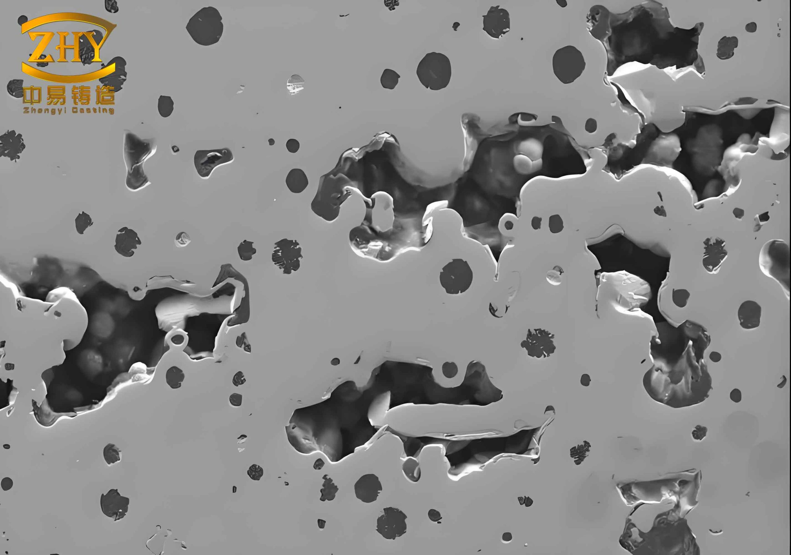
The complexity of defects, as illustrated, underscores the importance of a systematic approach. While this image may depict classic sand casting defect forms like gas holes and shrinkage, the underlying principles of fluid flow, heat transfer, and solidification are universal. In metal mold casting, these phenomena are accelerated and constrained, leading to distinct but related manifestations.
3. Surface Sweat (Exudation) or “Beading”
This defect appears as small, solidified droplets or beads on the casting surface. It is a direct consequence of the high internal pressure generated during the graphite expansion phase of solidification, coupled with specific process conditions. In sand casting, the mold wall can often yield or allow gas escape, mitigating this pressure. The rigid, impermeable metal mold offers no such relief.
Two primary scenarios cause surface sweat:
- Premature Mold Opening: If the mold is opened while the casting core is still partially liquid, the external pressure on the solid shell is released. The continued graphite expansion can then force the residual low-melting-point liquid iron through the interdendritic channels of the semi-solid shell, exuding onto the surface.
- Localized Slow Cooling: Areas with uneven coating, poor venting (causing air gap formation), or thicker geometry cool slower. These regions solidify last, and the expansion pressure from the rest of the casting can focus on pushing liquid from these “hot spots” to the surface.
The prevention is straightforward but requires strict process discipline. The mold opening time must be strictly controlled and calibrated to the specific casting mass and section thickness, ensuring complete solidification. For localized sweating, maintaining a uniform, thin coating layer and ensuring proper mold cooling to eliminate “hot spots” are critical.
4. Gas Porosity, Slag Porosity, and Slag Pinholes
This category of defects is arguably the most critical and common challenge in metal mold casting, representing a significant escalation of typical sand casting defect concerns. The impermeability of the mold is the dominant factor.
The defects can be classified by origin:
- Precipitation Porosity: Caused by dissolved gases (primarily hydrogen and nitrogen) coming out of solution as the iron solidifies. It is favored by high melt gas content from damp charge materials or inadequate superheating/holding.
- Entrainment Porosity & Slag Porosity: Caused by turbulent filling that entraps air or slag particles from the surface oxide layer. A poorly designed gating system is the usual culprit.
- Slag Pinholes (Reaction Porosity): A unique defect observed on upper vertical surfaces. It is caused by slag (often rich in FeO) sticking to the mold wall. The carbon from the mold coating (acetylene soot) or the iron reduces the oxide, generating CO gas. The rapid solidification prevents the bubble from floating away, instead forming a long, narrow, smooth-walled pore perpendicular to the surface.
The gas content in the melt is a function of initial charge conditions and melt treatment. The final hydrogen content \([H]\) can be related to atmospheric humidity and temperature by an expression akin to Sieverts’ Law, influenced by alloy composition:
$$
[H] \propto K_H \cdot \sqrt{P_{H_2O}}
$$
where \( K_H \) is a temperature-dependent equilibrium constant and \( P_{H_2O} \) is the partial pressure of water vapor from the atmosphere or damp materials.
The gating system design is paramount. A well-designed system for metal molds should:
1. Be bottom-gated or tilt-poured to ensure laminar fill.
2. Have a fully open (unchoked) profile to minimize turbulence.
3. Incorporate effective slag traps, such as filter grids at the sprue base or whirl gates.
4. Have vent areas (risers, vent slots) with a total cross-section at least 1.5 to 2 times that of the ingates to allow rapid gas expulsion.
A comprehensive prevention table is essential:
| Defect Type | Root Causes | Integrated Preventive Measures |
|---|---|---|
| Precipitation Porosity | High gas content in melt; low pouring temp; thick sections. | Dry all charge materials and tools; implement melt superheating and holding; use degassing fluxes if necessary. |
| Entrainment Porosity & Slag | Turbulent filling; ineffective slag trapping. | Design gating for laminar flow (bottom gating, open system); use ceramic filters; pour at consistent, moderate speed. |
| Slag Pinholes | Oxidic slag sticking to mold; residual carbon soot on mold surface. | Maintain clean mold surfaces; minimize slag formation by reducing turbulence and iron oxidation; control coating application. |
| General Gas Defects | Inadequate mold venting. | Ensure vent area > 1.5x ingate area; add vent slots at high points and blind pockets. |
5. Surface Laps or “Clips”
This defect resembles a severe cold shut but is actually a subsurface flaw. A thin layer of metal separates from the main body, revealing a concave pit. It occurs on upper flat surfaces or at junctions. The mechanism involves the final liquid, enriched in low-melting-point constituents (carbon, phosphorus), being forced under high expansion pressure through the dendritic network of the already-solidified surface layer. This liquid then spreads between the casting and the mold wall, forming a thin, fragile layer.
Key contributing factors are:
- Localized Slow Cooling (Hot Spots): Caused by uneven mold coating, residual thick carbon soot from acetylene smoking, or trapped air pockets. These areas have a coarser dendritic structure with wider channels, making it easier for liquid to be extruded.
- Alloy Chemistry: A lower Carbon Equivalent (CE) results in a more developed, extensive dendritic network during solidification, providing more paths for liquid extrusion. This makes thin-walled castings, or those with variable sections, particularly susceptible.
The mitigation strategy involves attacking both causes:
1. Uniform Cooling: Maintain a consistent, thin mold coating. Ensure proper mold cooling (e.g., water lines) to eliminate hot spots. Improve venting to prevent air pockets.
2. Alloy Adjustment: For castings prone to this defect (typically thinner-walled ones), slightly increase the CE within specification to reduce the dendrite coherency and the volume of late-stage liquid. For castings with high section variation, tight control of CE is critical.
6. Additional Considerations: Chilling and Shrinkage
While not the primary focus of the source material, chilling (formation of cementite instead of graphite) and shrinkage porosity are classic sand casting defect concerns that transform under metal mold conditions.
Chilling is promoted by the extremely high cooling rate, especially in thin sections or at sharp corners. The critical cooling rate \( \dot{T}_{crit} \) for white iron formation depends on CE and nucleation potential:
$$
\dot{T}_{crit} = f(CE, [Inoculant], [S])
$$
To prevent chilling, one must ensure sufficient graphitization potential. This is achieved by:
– Using effective inoculation (e.g., FeSi with Sr, Ba, Bi).
– Maintaining adequate CE for the section thickness.
– Ensuring the mold coating provides sufficient thermal insulation.
Shrinkage Porosity in metal molds is often more localized than in sand castings due to directional solidification. The lack of yield in the mold means feeding must be absolutely efficient. The famous Niyama criterion, often used for predicting sand casting defect shrinkage, is still applicable but with different boundary conditions:
$$
G / \sqrt{\dot{T}} \geq C
$$
where \( G \) is the temperature gradient, \( \dot{T} \) is the cooling rate, and \( C \) is a constant. In metal molds, \( G \) is very high near the wall but can drop quickly in heavier sections. The key is to design the gating and risering (where possible) to maintain a positive temperature gradient toward the feeder until the very end of solidification. In many vertical parting metal molds, this is achieved by placing the ingates at the bottom and large vent/feed heads at the top, creating a controlled directional solidification path.
Conclusion
The production of high-integrity cast iron components via metal mold casting is a balancing act that requires deep process understanding. Defects such as non-conforming graphite morphology, phosphorus banding, surface exudation, various forms of porosity, and surface laps are not random failures but direct consequences of the interplay between alloy chemistry, melt treatment, mold design, and process parameters. Many of these issues are intensified versions or specific variants of known sand casting defect phenomena, shaped by the unique constraints of the metal mold environment.
Successful mitigation is never about a single “magic bullet.” It is a systematic approach involving:
1. Rigorous control of charge materials and melting practice to manage nucleation and gas content.
2. Meticulous design of the gating and venting system to ensure laminar, quiescent filling and effective gas/slag removal.
3. Precise control of process variables such as pouring temperature, coating thickness, and mold opening time.
4. Tailoring alloy composition (particularly CE and inoculation) to the specific casting geometry and the cooling power of the mold.
By viewing defects through the lens of solidification science and fluid dynamics, and by learning from both the similarities and differences with sand casting defect mechanisms, one can develop robust, controlled metal mold casting processes capable of producing reliable, high-performance components consistently.