The premature solidification at the intersection of the inner runner and the investment casting of the turbine guide in the initial gating system can reduce the loss of the molten metal temperature by adding insulating cotton at the gating system. Secondly, for the shrinkage defects at the top of the inner and outer rings, the feeding riser can be set at the top of the inner runner to increase the feeding capacity of the inner runner. According to the defects of the top-pouring pouring system, a riser is reasonably set at the corresponding hot spot, and 10 mm thick thermal insulation cotton is wrapped outside the pouring system. The final optimized pouring system design is shown in Figure 1.

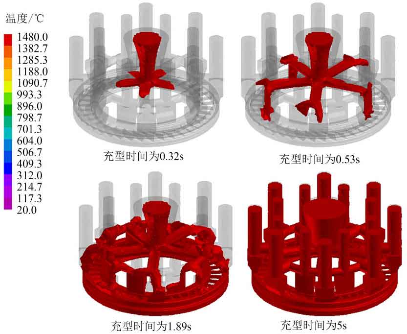
The filling process of the casting system of the investment casting of the turbine guide is shown in Figure 2. Under the action of gravity, the liquid metal first flows through the gate cup to five transverse runners, and then fills the inner and outer rings through the inner runner below the transverse runner. The inner and outer rings introduce the liquid metal into the inner blade forming area. The whole filling process is relatively stable, without splash and obvious turbulence. The mold filling simulation time is 5 s. Select different mold filling time (0.32, 0.53, 1.89, 5 s) to observe the melt mold filling. It can be seen that when the mold filling time reaches 0.32 s, the molten metal enters the transverse runner through the gating cup, and the color band is uniform as a whole, without splash and other phenomena; When the filling time reaches 0.53 s, the molten metal begins to flow from the transverse runner to the inner runner, and the cross part of the transverse runner and the inner runner may cause uneven volume shrinkage due to temperature difference, resulting in shrinkage porosity and shrinkage holes and other defects; When the filling time is 1.89 s, the liquid metal has started to fill the entire cavity, and the final filling time is 5 s. The liquid metal completely fills the cavity, and the filling effect is good. Under the joint action of the two kinds of internal sprues, the whole mold cavity can be filled by the liquid metal in the inner and outer rings.
The mold filling process of the turbine guide casting is shown in Figure 3. The molten metal first flows from the inner runner close to the transverse runner to the inner ring of the casting to be formed, and then flows smoothly from the inner ring to the blade forming area. Then the inner runner far from the transverse runner fills the inner ring and the outer ring with molten metal respectively until the inner ring is filled. At this time, the molten metal at the inner ring is not solidified, Continue to flow to the unfilled part of the blade forming area until the metal liquid in the inner and outer rings is filled for the blade forming area, and the outer ring is the position where the melt is finally filled, and then the whole cavity is filled, and the filling process is stable without splash. The above mold filling simulation results show that this pouring process can eliminate the turbulence phenomenon of turbine guide vane.
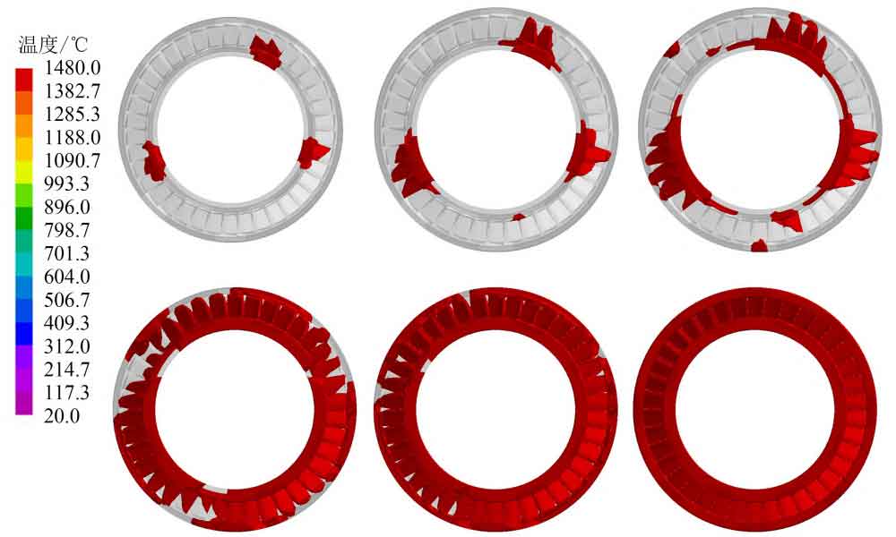
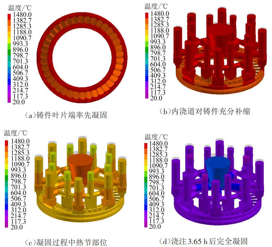
Fig. 4 shows the simulation results of temperature field distribution during solidification of investment casting of turbine guide. It can be seen from Figure 4 (a) that the pouring scheme can start from the blade end of the investment casting of the turbine guide. In Figure 4 (b), the metal liquid in the inner and outer rings of the casting can ensure the feeding in the blade, and then the inner and outer rings start to solidify, and the feeding is carried out through the inner runner. The last inner runner and the transverse runner start to solidify. From Figure 4 (c), it can be seen that the solidification time of the cross part of the transverse runner and the inner runner is relatively late, The temperature in the wall thickness area is high, which is easy to produce hot spots and shrinkage porosity, but the pouring system is sufficient to feed the cavity during solidification. The solidification of the investment casting of the turbine guide presents a sequential solidification process from the inside to the outside. The solidification begins at the thin-walled part of the investment casting of the turbine guide, advances gradually to the medium-thick part, and finally solidifies at the part connected with the inner runner. Compared with the temperature color band on the left, the temperature difference between the highest liquid temperature and the lowest liquid temperature in the mold exceeds 100 ℃ during the solidification of the investment casting of the turbine guide. This is mainly caused by the uneven wall thickness of the investment casting of the turbine guide. If the feeding is not timely or sufficient, defects such as porosity or insufficient pouring will occur. The final solidification time of the solidification temperature field of the whole gating system is 3.65 h, as shown in Figure 4 (d).