
In this study, I explore the application of lost foam casting for producing rump pan components used in scraper conveyors, focusing on addressing common defects such as shrinkage porosity, misruns, and cold shuts. Lost foam casting is a advanced manufacturing technique that offers significant advantages over traditional sand casting, including reduced environmental impact, simplified processes, and improved surface quality. Through numerical simulation using specialized software, I analyze the casting process, identify potential issues, and optimize the工艺 to enhance product quality. The关键词 “lost foam casting” will be frequently emphasized throughout this discussion to highlight its relevance.
Lost foam casting involves creating a foam pattern of the desired part, which is then coated with a refractory material and embedded in unbonded sand. During pouring, the foam vaporizes, allowing molten metal to fill the cavity. This method eliminates the need for cores and reduces post-casting清理, making it ideal for complex geometries like the rump pan. However, challenges such as uneven cooling and gas evolution can lead to defects. My investigation employs simulation tools to model the filling and solidification processes, enabling predictive analysis and optimization.
The rump pan, a critical component in coal mining equipment, has a complex structure with varying wall thicknesses, ranging from 25 mm to 60 mm. This non-uniformity often results in thermal gradients during solidification, promoting shrinkage defects. The material used is ZG30SiMn steel, which requires precise control over casting parameters to achieve desired mechanical properties. In lost foam casting, the design of the gating system and risers plays a vital role in ensuring complete filling and effective feeding. I begin by examining an initial process scheme and then propose optimizations based on simulation insights.
To model the lost foam casting process, I use fundamental equations of fluid dynamics and heat transfer. The filling process can be described by the Navier-Stokes equations, while solidification involves the heat conduction equation. For instance, the energy balance during solidification is given by:
$$ \frac{\partial (\rho c_p T)}{\partial t} = \nabla \cdot (k \nabla T) + L \frac{\partial f_s}{\partial t} $$
where \( \rho \) is density, \( c_p \) is specific heat, \( T \) is temperature, \( k \) is thermal conductivity, \( L \) is latent heat, and \( f_s \) is the solid fraction. In lost foam casting, additional factors like foam decomposition and gas pressure must be considered, but for simplicity, I focus on thermal aspects. The simulation parameters include a pouring temperature of 1600°C, liquidus temperature of 1512°C, solidus temperature of 1470°C, and a mold-sand interface heat transfer coefficient of 800 W/(m²·K).
The initial process design for the lost foam casting of the rump pan featured a top-gating system with a sprue diameter of 60 mm and ingate diameter of 50 mm, along with a riser for feeding. The mold was tilted at approximately 3° to facilitate sand compaction and riser effectiveness. However, simulation results revealed several issues. The filling process showed uneven temperature distribution, with cooler regions forming at the M-groove connections, leading to potential misruns. During solidification, shrinkage porosity was predicted in thick sections, such as the base-plate and rib junctions, due to inadequate feeding from the riser.
A detailed analysis of the initial scheme’s solidification sequence indicated that liquid metal remained isolated in central areas after 881.4 seconds, resulting in shrinkage defects. The table below summarizes key simulation parameters and observed defects for the initial lost foam casting process:
| Parameter | Value | Observation |
|---|---|---|
| Pouring Temperature | 1600°C | High fluidity but rapid cooling in thin sections |
| Filling Time | 30 s | Uneven flow leading to cold shuts |
| Solidification Time | 2545.9 s | Shrinkage porosity in thick zones |
| Riser Design | Single riser | Insufficient feeding for large planar areas |
To address these issues, I optimized the lost foam casting process by reorienting the casting position. The M-groove was placed vertically, and the thick plate section was positioned at the top, with additional risers at both ends to improve feeding. This change promoted directional solidification, where thicker sections solidify last, allowing risers to compensate for shrinkage. The gating system was modified to include multiple ingates for better metal distribution. The optimized lost foam casting scheme resulted in a more uniform temperature profile during filling, as shown in the simulation, with minimal thermal gradients.
The improved lost foam casting process demonstrated a stable filling sequence, with metal initially filling the M-groove base and gradually moving upward. By 60% filling, the M-groove was fully occupied, and the thick plate section filled evenly. The solidification analysis confirmed that risers remained effective until the end, with liquid metal available for feeding critical areas. The final solidification time was approximately 2591.6 seconds, and shrinkage defects were significantly reduced, particularly at the shovel plate and rib connections. The table below compares the initial and optimized lost foam casting parameters:
| Aspect | Initial Process | Optimized Process |
|---|---|---|
| Orientation | M-groove down | M-groove vertical |
| Riser Count | 1 | 2 (including sprue) |
| Filling Uniformity | Poor | Excellent |
| Shrinkage Defects | High in thick zones | Minimal |
In lost foam casting, the vaporization of the foam pattern introduces complexities that can be modeled using additional equations. For example, the rate of foam decomposition can be expressed as:
$$ \frac{dm_f}{dt} = -A \exp\left(-\frac{E_a}{RT}\right) $$
where \( m_f \) is the foam mass, \( A \) is a pre-exponential factor, \( E_a \) is activation energy, \( R \) is the gas constant, and \( T \) is temperature. Although this study focuses on thermal simulations, such factors are crucial for accurate predictions in real-world lost foam casting applications.
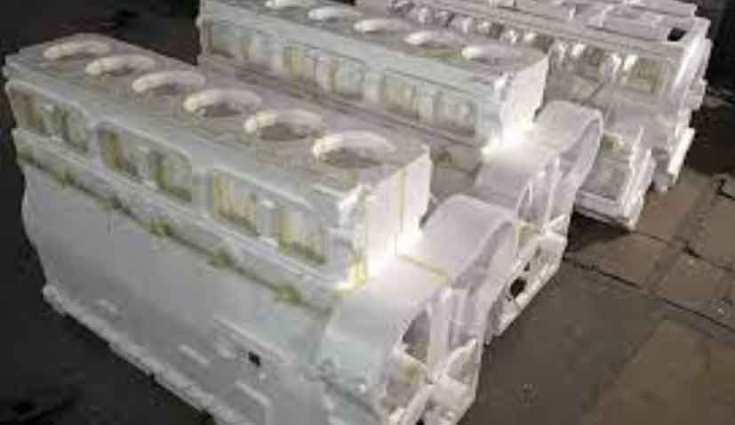
Experimental validation of the optimized lost foam casting process was conducted through batch production. The EPS patterns were manufactured, and castings were produced under controlled conditions. Post-casting inspection revealed no significant defects such as shrinkage porosity, gas holes, or misruns. The internal structure near the risers showed sound metal with no voids, confirming the effectiveness of the feeding system. This success underscores the importance of numerical simulation in optimizing lost foam casting for complex components like the rump pan.
The benefits of lost foam casting extend beyond defect reduction. This method reduces labor costs and environmental impact by eliminating binders and simplifying sand recycling. In the context of the rump pan, lost foam casting ensures high dimensional accuracy and surface finish, which are critical for subsequent welding and assembly operations. My analysis shows that by integrating simulation-driven design, lost foam casting can achieve superior results compared to traditional methods.
In conclusion, this study demonstrates the efficacy of numerical simulation in optimizing the lost foam casting process for rump pan production. The initial scheme suffered from shrinkage defects due to poor feeding, but the optimized design, with improved orientation and riser placement, eliminated these issues. The repeated emphasis on “lost foam casting” throughout this discussion highlights its versatility and potential for industrial applications. Future work could explore advanced modeling techniques to incorporate foam decomposition dynamics, further enhancing the accuracy of lost foam casting simulations.
Overall, lost foam casting proves to be a robust method for manufacturing high-integrity components. By leveraging simulation tools, manufacturers can predict and mitigate defects, leading to higher quality products and reduced development time. The insights gained from this rump pan case study can be applied to other complex castings, promoting wider adoption of lost foam casting in various industries.