
In the realm of industrial machinery, bearing housings serve as critical structural components for supporting bearings. They are essential auxiliary transmission parts that secure the outer ring of a bearing, enabling the inner ring to perform continuous, high-precision rotation about its axis. This function is paramount for reducing friction, thereby significantly enhancing the operational lifespan of the bearing and improving the overall efficiency and reliability of the equipment. The precision of a bearing housing, particularly its inner bore and base plate, is intrinsically linked to the accuracy of the entire transmission process. The inner bore provides crucial support and positioning for the bearing, while the base plate acts as the primary mounting and load-bearing surface. Any compromise in the quality or improper installation of the base plate can lead to failure under operational stresses. The production of high-integrity gray iron castings, such as these housings, demands meticulous process design to avoid internal defects like shrinkage porosity and cavities, which can severely impact performance.
Traditionally, casting process development relied heavily on the “trial-and-error” method, which is often time-consuming, resource-intensive, and costly. The advent of numerical simulation technology has revolutionized this paradigm. By supplementing traditional approaches with simulation tools, foundry engineers can visualize the entire casting process—filling and solidification—before any metal is poured. This not only saves substantial manpower and material resources but also drastically shortens the development cycle, leading to more robust and optimized processes for gray iron castings. This article details the application of ProCAST simulation software to design and optimize the sand casting process for the upper half of an HT250 bearing housing. By analyzing the results of initial simulations, the process was systematically optimized using risers and chills, establishing a reliable theoretical foundation for practical production.
Process Analysis of the Gray Iron Casting
The upper half of the bearing housing, a quintessential example of a complex gray iron casting, presents several challenges for the foundry engineer. Its three-dimensional geometry features an outer轮廓尺寸 of approximately 1085 mm x 910 mm x 380 mm. A key characteristic is the significant variation in wall thickness, ranging from a minimum of 20 mm to a maximum of 145 mm, with an average around 25 mm. This disparity inevitably leads to the formation of hot spots in the thicker sections, as these regions cool much slower than thinner walls. During solidification, these hot spots can become isolated liquid pools, leading to shrinkage defects if not properly fed. The part features a large internal cavity and a substantial flat base plate, which is a critical machining and load-bearing surface. The material specified is HT250 gray iron, with a finished casting weight of 566 kg. For such a medium-sized casting produced in low volumes, green sand or chemically bonded sand casting offers the necessary flexibility, cost-effectiveness, and technical maturity. In this case, acid-cured furan resin no-bake sand was selected for its excellent thermal stability, bench life, and suitability for small-batch iron casting production.
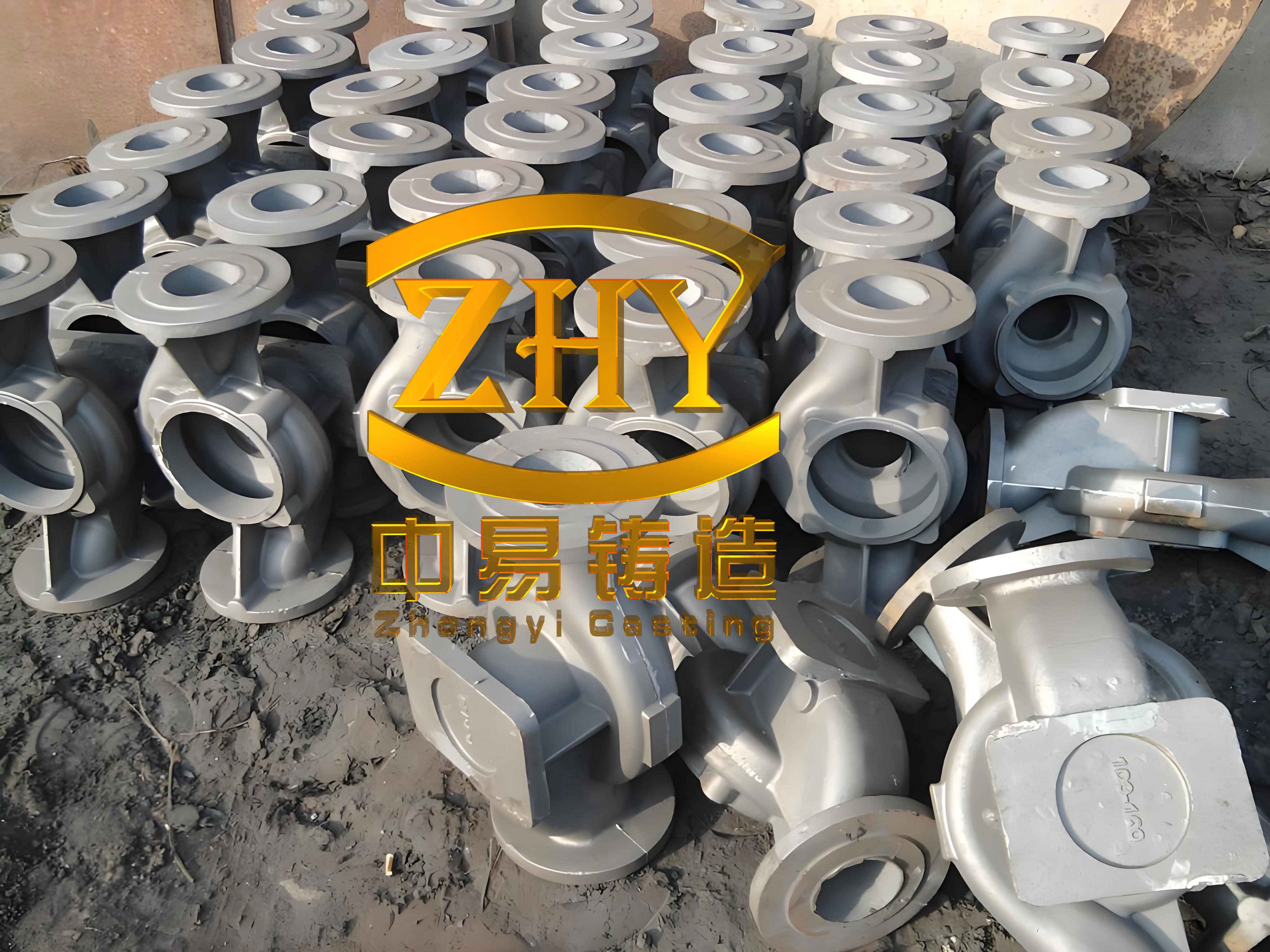
The choice of HT250 is strategic. Gray iron castings derive their name from the flake graphite present within a primarily pearlitic matrix. This microstructure grants the material a favorable combination of properties: good tensile strength, excellent wear resistance, damping capacity, and thermal conductivity. A unique advantage of gray iron during solidification is the expansion associated with graphite precipitation. As the graphite flakes grow during the eutectic reaction, they displace the surrounding liquid, effectively counteracting a portion of the metal’s liquid and solidification shrinkage. This characteristic, often referred to as “self-feeding” to a degree, reduces—but does not eliminate—the demand for external feed metal compared to alloys like steel. The solidification sequence involves the precipitation of primary austenite dendrites followed by the eutectic transformation of the remaining liquid into austenite-graphite aggregates (eutectic cells). Proper process design must orchestrate this solidification to utilize the expansion effectively while ensuring all sections are sound.
The typical chemical composition range for HT250 gray iron castings is summarized in the table below:
| Element | Carbon (C) | Silicon (Si) | Manganese (Mn) | Phosphorus (P) | Sulfur (S) |
|---|---|---|---|---|---|
| Content (wt.%) | 3.1 – 3.4 | 1.8 – 2.2 | 0.6 – 0.9 | < 0.15 | < 0.12 |
Casting Process Design Methodology
The design of a casting process is a multi-step procedure that begins with determining the optimal position for the casting within the mold and the layout of the gating and feeding systems. For this bearing housing gray iron casting, three initial pouring position schemes were considered based on fundamental principles: ensuring critical surfaces are oriented to minimize defects, facilitating mold assembly, and promoting directional solidification towards feed metal sources.
Scheme 1 oriented the large base plate downward. This offers several advantages: it promotes better surface quality on this critical machined face, simplifies core placement and positioning, and places the thickest sections in the upper parts of the mold, which is ideal for placing feeding risers. A potential drawback is increased complexity in pattern drawing, possibly requiring more loose pieces.
Scheme 2 placed the largest thin-walled section at the bottom to ensure complete filling, while thick sections remained on top for feeding. However, this could compromise the quality of critical upper surfaces and result in an excessively tall mold flask, complicating handling.
Scheme 3 positioned a critical machined face on the side, which can help prevent slag and sand inclusions. Nevertheless, it creates an overhanging “cantilever” core, making it difficult to ensure the soundness of the heavy base plate section.
After evaluation, Scheme 1 was selected as it best balances quality requirements for the gray iron casting with practical mold-making considerations.
The parting line was set at the bottom plane of the housing. This simple two-part mold (cope and drag) design encapsulates the entire casting in the drag, maximizing dimensional accuracy by avoiding misalignment across the parting plane and simplifying molding operations.
Gating System Design and Calculation
A bottom-gating system was designed to introduce molten iron into the mold cavity calmly from below. This approach minimizes turbulence, oxide formation, and sand erosion, which is crucial for producing clean gray iron castings. A pressurized gating system (where the choke is at the smallest cross-section, typically the ingates) was chosen to promote rapid filling and a well-defined metallostatic head. The cross-sectional area ratios for the system were set as: $$\sum A_{\text{sprue}} : \sum A_{\text{runner}} : \sum A_{\text{ingate}} = 1.15 : 1.1 : 1.0$$.
The first critical calculation is the pouring time \( t \). For gray iron castings weighing between 100 and 1000 kg, an empirical formula is often used:
$$ t = S_1 \sqrt[3]{G_L} $$
where:
\( t \) = pouring time (s),
\( S_1 \) = empirical coefficient (taken as 1.7 for fast pouring),
\( G_L \) = total mass of metal in the mold (kg).
The casting mass is 566 kg. Accounting for the gating system, the total poured mass \( G_L \) is estimated at 1.2 times the casting weight, or 679.2 kg.
$$ t = 1.7 \times \sqrt[3]{679.2} \approx 1.7 \times 8.75 \approx 46.4 \text{ seconds} $$
Next, the choke area \( A_{\text{choke}} \) (assumed to be the total ingate area \( \sum A_{\text{ingate}} \)) is calculated using the Ozan (or Bernoulli) formula, which balances the metallostatic pressure head with the flow resistance through the gating system:
$$ A_{\text{choke}} = \frac{G_L}{\rho \cdot \mu \cdot t \cdot \sqrt{2gH_p}} $$
Where \( \rho \) is the liquid iron density (~7000 kg/m³), \( \mu \) is the discharge coefficient (~0.55 for iron in sand molds), \( g \) is gravity (9.81 m/s²), and \( H_p \) is the effective metallostatic head (m). For a bottom-gated system, \( H_p \) is approximately the height from the top of the sprue to the ingate. Based on the mold geometry and calculation, the required choke area was found to be 8.75 cm². Applying the predetermined ratios:
$$ \sum A_{\text{sprue}} = 1.15 \times 8.75 \approx 10.06 \text{ cm}^2 \quad \Rightarrow \quad \text{Sprue Exit Diameter } D_{sprue} = 36 \text{ mm} $$
$$ \sum A_{\text{runner}} = 1.1 \times 8.75 \approx 9.63 \text{ cm}^2 $$
$$ \sum A_{\text{ingate}} = 1.0 \times 8.75 = 8.75 \text{ cm}^2 $$
The final dimensions for the gating system are presented in the table below:
| Gating Element | Design Type | Calculated Area (cm²) | Final Dimensions (mm) |
|---|---|---|---|
| Sprue (Exit) | Cylindrical | 10.06 | Ø 36 |
| Runner | Trapezoidal | 9.63 | 30 x 25 (avg.) |
| Ingates | Rectangular | 8.75 (total) | 4 ingates, each ~47 x 47 |
Numerical Simulation and Initial Defect Prediction
The initial process design, while theoretically sound, requires validation. Using ProCAST simulation software, the filling and solidification sequences were analyzed. The 3D model was meshed, and boundary conditions were applied: a pouring temperature of 1350°C, a pour time of 46.4 s, and an initial mold and core temperature of 20°C. The simulation of the filling process confirmed a smooth, progressive fill from the bottom up, taking approximately 47.7 seconds, which aligns well with the calculated 46.4 seconds. The temperature distribution during filling showed minimal heat loss in the initial stages, with the gates solidifying around 404 seconds after the start of the pour, marking the end of the feeding period from the gating system.
The solidification analysis revealed five distinct thermal centers or hot spots, primarily located in the thickest sections of the casting. These are regions that remain liquid longest and are most susceptible to shrinkage formation if not adequately fed. The subsequent defect prediction module, which uses the “Fraction Solid” or “Porosity” criteria, clearly identified these hot spots as locations with a high probability of macro-shrinkage. The most severe predicted defect was located at the central, thickest section of the casting. This simulation outcome confirmed the necessity of implementing a feeding system (risers) complemented by chilling to control the solidification pattern for these gray iron castings.
Process Optimization Using Risers and Chills
To address the predicted shrinkage, the principle of directional solidification was applied. The goal is to establish a temperature gradient where the casting sections solidify first, followed progressively by thicker sections, and finally the risers themselves. This ensures a continuous feed path of liquid metal to compensate for shrinkage. For gray iron castings, riser design must consider the compensatory effect of graphite expansion. The “Modulus Method” or “Sectional Proportionality Method” is commonly employed. The riser’s modulus (Volume/Surface Area ratio) must be greater than that of the casting section it is intended to feed.
Two top, open risers were designed. Their dimensions are based on the thermal modulus of the hot spots they are intended to feed. The general formulas for an open top riser are:
$$ D_R = K \cdot T $$
$$ H_R = (1.2 \text{ to } 2.5) \cdot D_R $$
where \( D_R \) is the riser diameter, \( T \) is the thermal diameter (or thickness) of the hot spot, \( K \) is a coefficient (typically 1.2-2.0, chosen as 1.5 here), and \( H_R \) is the riser height. For the main central hot spot (\( T_1 \approx 66.5 \text{ mm} \)):
$$ D_{R1} = 1.5 \times 66.5 \approx 100 \text{ mm}, \quad H_{R1} = 1.5 \times 100 = 150 \text{ mm} $$
For a secondary hot spot (\( T_2 \approx 50 \text{ mm} \)):
$$ D_{R2} = 1.5 \times 50 = 75 \text{ mm}, \quad H_{R2} = 1.5 \times 75 = 112.5 \text{ mm} $$
The neck dimensions are designed to facilitate feeding and allow easy removal.
Concurrently, six external chills were strategically placed on the drag side of the mold, adjacent to thicker sections of the casting. Chills are pieces of high-thermal-conductivity material (e.g., cast iron) that accelerate localized cooling. They help eliminate secondary hot spots, extend the effective feeding range of risers, and promote the desired temperature gradient. The thickness of a chill is typically 0.5 to 1.0 times the thickness of the casting section it contacts. For this initial optimization, chills of 10 mm thickness were applied.
| Optimization Element | Quantity | Primary Function | Key Design Parameter |
|---|---|---|---|
| Insulating Riser #1 | 1 | Feed central heavy section | Ø100 x 150 mm |
| Insulating Riser #2 | 1 | Feed rear thick section | Ø75 x 112.5 mm |
| External Chills (1-6) | 6 | Accelerate cooling, eliminate hot spots | 10 mm thickness |
The simulation was rerun with this optimized setup. The results showed marked improvement. The size and volume of predicted shrinkage defects within the casting body were significantly reduced. Most of the remaining defect volume was successfully shifted into the risers, indicating they were performing their feeding function effectively. However, analysis of the temperature field slice near Riser #1 revealed a lingering, elongated high-temperature zone adjacent to it, which correlated with a remaining area of predicted shrinkage in the casting. This indicated that the solidification sequence was not fully optimal in that region.
Secondary Optimization
To address the remaining issue, a seventh, thicker chill (Chill #7) was added specifically to the problematic area next to Riser #1. Given the substantial thermal mass of this junction, a chill thickness of 30 mm was specified. The simulation of this final configuration yielded excellent results. The defect prediction showed that virtually all significant shrinkage porosity was now contained within the risers. The casting body itself was predicted to be sound, demonstrating a successful directional solidification pattern achieved through the synergistic use of risers and chills. This multi-step optimization process underscores the power of simulation in iteratively refining the process for complex gray iron castings.
Conclusion
This study demonstrates a systematic approach to designing and optimizing the casting process for a critical industrial component. Through a detailed analysis of the bearing housing’s geometry and material characteristics, an initial sand casting process was designed, featuring a bottom-gating system. ProCAST numerical simulation was then employed as a virtual testing ground, accurately predicting the locations of shrinkage defects in the initial design. Guided by the principle of directional solidification, the process was optimized through the strategic placement of two insulating risers and seven external chills. A secondary optimization, prompted by detailed temperature field analysis, involved adding a specific, thicker chill to perfect the solidification sequence.
The final simulation results confirmed that the optimized scheme successfully redirected shrinkage into the risers, ensuring the internal soundness of the bearing housing gray iron casting. This work highlights that numerical simulation is an indispensable tool for modern foundries. It enables a deep understanding of the complex thermal processes involved, allowing for rapid, cost-effective, and data-driven optimization of casting parameters. This methodology not only improves the quality and yield of gray iron castings but also accelerates the time-to-market for new components, providing a solid theoretical and practical foundation for manufacturing reliable, high-performance castings.