
As a casting engineer tasked with developing a reliable and cost-effective production process, I often encounter components where traditional trial-and-error methods are prohibitively expensive and time-consuming. The subject of this analysis is a critical grey iron casting: the upper half of a large bearing housing. This component is fundamental in power transmission systems, serving to secure the bearing outer race, enabling precise rotation of the inner race, minimizing friction, and thereby enhancing the overall reliability and service life of the machinery. The dimensional accuracy of its bore and base mounting surfaces is paramount for the entire assembly’s performance. This article details my first-person approach to designing, simulating, and optimizing the grey iron casting process for this part using numerical simulation as a core tool, effectively replacing costly physical prototypes with virtual ones.
The component, modeled in 3D CAD software, presents significant challenges typical of complex grey iron casting. Its overall envelope dimensions are approximately 1085 mm x 910 mm x 380 mm. The wall thickness is highly variable, ranging from a minimum of 20 mm to a maximum of 145 mm around the central boss, with an average near 25 mm. This disparity creates pronounced thermal mass differences, inevitably leading to hot spots and a high risk of shrinkage porosity in the heavier sections. The part features a large, open interior cavity, necessitating a substantial sand core. The specified material is grade HT250, a flake graphite grey iron known for its good strength, wear resistance, damping capacity, and—most importantly for grey iron casting—its unique solidification behavior involving graphite expansion that can counteract liquid shrinkage. The finished casting weight is 566 kg, placing it in the medium-to-large category for jobbing foundries.
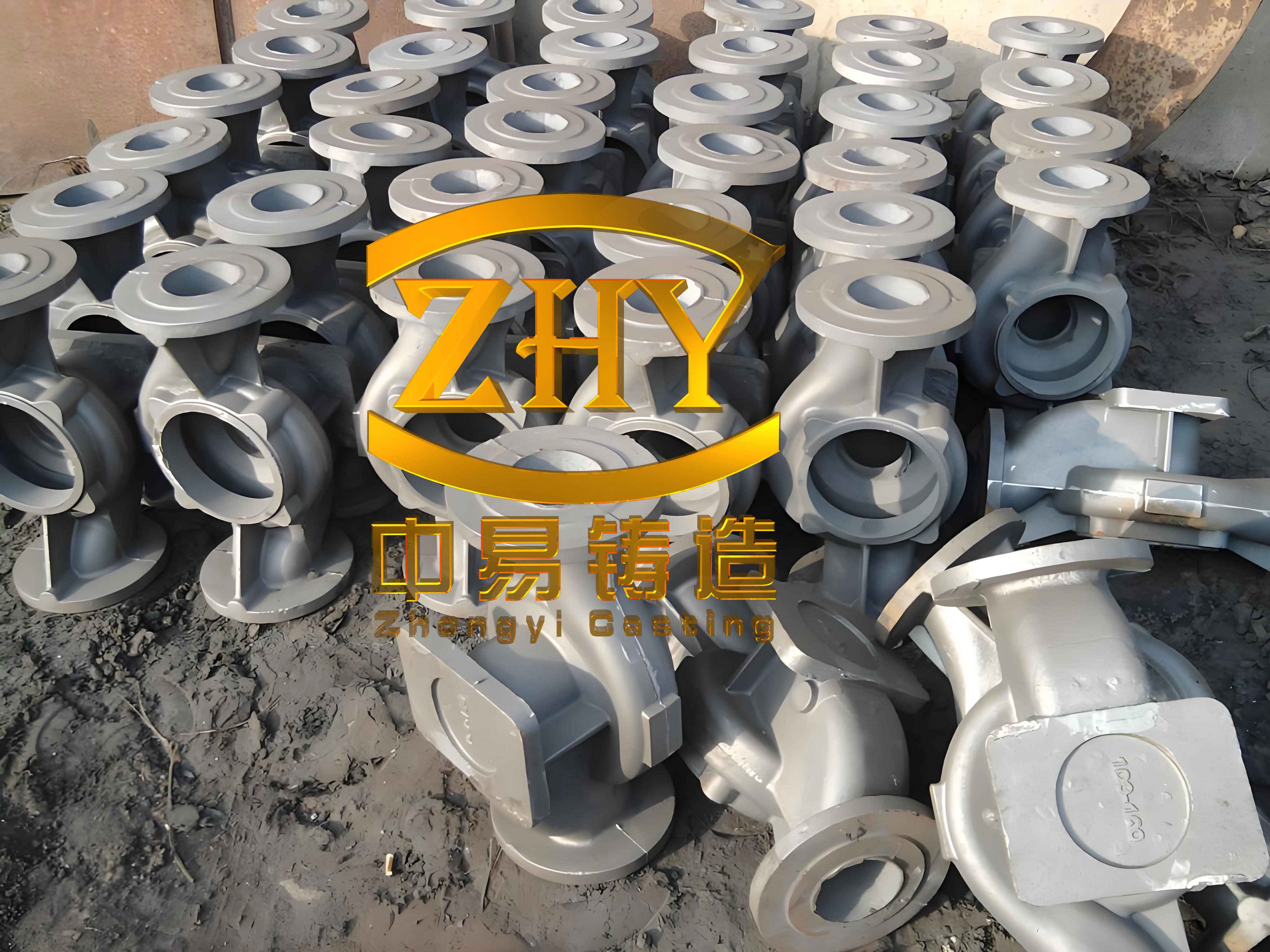
The selection of HT250 for this grey iron casting is strategic. Its key properties and typical composition are summarized below, which directly influence gating and feeding design decisions.
| Element | Composition (wt.%) | Key Property | Value (Typical) |
|---|---|---|---|
| C | 3.1 – 3.4 | Tensile Strength | 250 MPa (min) |
| Si | 1.8 – 2.1 | Hardness (HB) | 180 – 250 |
| Mn | 0.6 – 0.9 | Elastic Modulus | 105 – 140 GPa |
| P | < 0.15 | Damping Capacity | High |
| S | < 0.12 | Thermal Conductivity | ~50 W/(m·K) |
Given the part’s size, geometry, and low-volume production batch, green sand molding was deemed less suitable due to potential accuracy issues with the deep core. I selected acid-catalyzed furan resin-bonded sand for both the mold and core. This self-setting system offers excellent dimensional stability, good collapsibility, and is ideal for manual or semi-mechanized molding of complex jobbing castings like this grey iron casting. To prevent metal penetration and improve surface finish, an alcohol-based zircon coating was specified for the mold cavity surfaces.
Foundry Process Design: Rationale and Initial Calculations
The first critical decision was determining the pouring position. Three principal orientations were evaluated based on standard grey iron casting principles: placing critical surfaces downward to ensure quality, positioning heavy sections upward to facilitate feeding, and minimizing the use of loose pieces for moldability. The chosen orientation (Position 1) places the large, flat base of the housing at the bottom. This ensures the most critical machined and load-bearing surface is free from gross defects like slag inclusions or gas holes. While this orientation puts the massive central hub in an upper-middle location—creating a feeding challenge—it was preferred over alternatives that compromised the base quality or created unstable, hanging core conditions.
The parting plane was set at the very bottom edge of the casting’s base flange. This simple two-part mold scheme (cope and drag) encapsulates the entire casting geometry in the drag, with the cope forming the top of the base and the sprue/runner system. This maximizes dimensional accuracy by avoiding multi-part molds and minimizes mold-making complexity for this grey iron casting.
For the gating system, a pressurized, bottom-gating design was selected. This promotes a calm, progressive fill from the bottom up, minimizing turbulence and oxide formation—a crucial factor for clean grey iron casting. The system is designed as closed (choke at the sprue base) with a typical area ratio for grey iron: Sprue Exit : Runner : Ingate = 1.15 : 1.1 : 1. The key calculation is determining the choke area using the empirically-derived Oszwald formula, which for a grey iron casting of this mass is appropriate:
$$ t = S_1 \cdot \sqrt[3]{\delta \cdot G_L} $$
Where \( t \) is the pouring time (s), \( S_1 \) is an empirical coefficient (taken as 1.7 for quick pouring of grey iron), \( \delta \) is the average wall thickness (cm), and \( G_L \) is the total poured mass (kg). With a casting mass of 566 kg and a yield estimate of 1.2, \( G_L \) = 679.2 kg. An average wall thickness \( \delta \) of 2.5 cm was used. Solving for the choke area \( A_{choke} \) involves combining this with the fluid flow equation \( G_L = \rho \cdot A_{choke} \cdot \mu \cdot \sqrt{2gH} \cdot t \), where \( \rho \) is density, \( \mu \) is the discharge coefficient, \( g \) is gravity, and \( H \) is the metallostatic head. The calculated choke area was 8.75 cm². From this, the dimensions of the entire system were derived and standardized, as shown in the table below.
| Gating Element | Cross-Sectional Area (cm²) | Designed Dimensions (mm) | Function/Rationale |
|---|---|---|---|
| Sprue (Exit) | 10.06 | Ø 36 (Diameter) | Controls pour rate; tapered for non-aspiration. |
| Runner | 9.63 | 30 x 32 (Rectangular) | Distributes metal; first slag trap location. |
| Ingate (x4) | 8.75 total (2.19 each) | 17 x 13 (Rectangular, each) | Introduces metal calmly into mold cavity at base. |
Initial Numerical Simulation and Defect Prediction
With the initial process designed, I used ProCAST simulation software to virtually evaluate it. The 3D model of the casting, mold, and core was meshed, and boundary conditions were applied: a pouring temperature of 1350°C, mold initial temperature of 20°C, and the calculated pour time of 46.4 seconds. The simulation of this grey iron casting process provided profound insights.
The fill sequence confirmed a smooth, bottom-up progression. The fill time plot showed isochrones as layered bands, indicating minimal turbulence. The thermal analysis during solidification was the most critical output. By examining the solid fraction progression and temperature gradients, I identified five major thermal centers or hot spots, labeled H1 through H5. H1, at the massive central hub, was the most severe. The predicted shrinkage porosity for the initial “no-riser” design was alarming. Defects clustered precisely at these hot spots, with the largest volumetric shrinkage cavity predicted at H1. This confirmed the theoretical concern: isolated liquid pools forming in the last-to-freeze heavy sections, unable to be fed due to the early solidification of the thin-walled sections and gating system. The solidification sequence was anything but directional, which is problematic even for a grey iron casting where graphitic expansion offers some self-feeding. The expansion is often insufficient to compensate for the liquid shrinkage in such large, isolated thermal masses.
Optimization Strategy: Integrating Feeding and Chilling
The simulation clearly dictated the need for an optimized feeding system. The goal was to enforce a directional solidification sequence, starting from the extremities and thin walls toward the heavy sections, and finally into dedicated risers. For this grey iron casting, I employed a combination of insulating risers and external chills. The risers’ role is to remain molten longer than the casting, providing a reservoir of liquid metal to feed shrinkage. Chills act as heat sinks, accelerating solidification in specific areas to control the solidification path and extend the effective feeding range of a riser.
Riser design followed the “modulus method” in principle, adapted for grey iron casting. The modulus (Volume/Surface Area ratio) of the hot spot is calculated, and the riser is designed to have a larger modulus to ensure it solidifies last. For the two main hot spots H1 and H2, I designed top-mounted insulating sleeve risers. Their dimensions were based on the hot spot’s characteristic thickness \( T \). For a cylindrical hot spot, the riser diameter \( D_R \) and height \( H_R \) are given by:
$$ D_R = K \cdot T $$
$$ H_R = (1.2 \text{ to } 2.0) \cdot D_R $$
Where \( K \) is a factor typically between 1.2 and 2.5. For H1 (T ≈ 66.5 mm), K was chosen as 1.5, giving \( D_{R1} \) = 100 mm. For H2 (T ≈ 50 mm), \( D_{R2} \) = 75 mm. Their heights were initially set to 1.5 times their diameter. The neck dimensions were designed to ensure it freezes shortly after the casting hot spot to allow for feed metal transfer but also to enable easy removal. The common parameters for different riser types used in grey iron casting are summarized below.
| Riser Type | Key Design Parameters (as function of hot spot thickness T) | Application Context |
|---|---|---|
| Top Open Riser | \( D_R = (1.2-2.5)T \); \( H_R = (1.2-2.5)D_R \) | General purpose; easy topping up. |
| Side Riser (Open) | \( D_R = (1.2-2.5)T \); \( H_R = (1.2-2.5)D_R \); Neck section = \( (0.6-0.8)T \) | When top location is not feasible. |
| Side Riser (Blind) | \( D_R = (1.2-2.0)T \); \( H_R = (1.2-1.5)D_R \) | Used in machine molding; better yield. |
Simultaneously, I designed seven external chills. Their primary function was to accelerate the cooling of thicker sections adjacent to hot spots H3, H4, and H5, and to create a more favorable temperature gradient toward the risers at H1 and H2. The thickness of an external chill \( t_{chill} \) is critical; too thin and it becomes saturated with heat, too thick and it’s wasteful. A common rule of thumb for grey iron casting is:
$$ t_{chill} = (0.5 \sim 0.8) \times T_{hotspot} $$
For the various thinner ribs and walls (H3-H5), chills of 10 mm thickness were specified. Their faces were shaped to match the contour of the casting surface.
Simulation of Optimized Design and Iterative Refinement
I incorporated the two insulating risers and the seven chills into the ProCAST model and re-ran the solidification analysis. The results were markedly improved. The defects at the secondary hot spots H3, H4, and H5 were virtually eliminated, confirming the effectiveness of the chills. The major defect volume at H1 and H2 was significantly reduced and, crucially, had shifted location—it was now primarily contained within the riser bodies themselves. This is the ideal outcome in grey iron casting process optimization: defects are moved from the casting into the sacrificial risers, which are later removed. The solidification sequence showed a much clearer directional pattern, progressing from the chilled thin sections toward the risers.
However, a detailed examination of the temperature field slice through the H1 region revealed a lingering concern. A small but distinct elliptical high-temperature zone remained in the casting just adjacent to Riser 1, indicating a potential remnant hot spot. While the main shrinkage was in the riser, this area was at high risk for micro-porosity. To address this, I performed a second, targeted optimization. A single, additional chill (Chill #7) was designed for this specific location. Given the local thickness, its dimension was more substantial: a contoured chill with a thickness of 30 mm was placed against this specific region of the central hub.
The final simulation run, including this eighth chill, showed excellent results. The problematic high-temperature zone was effectively eliminated. The predicted shrinkage porosity was now almost entirely confined to the upper two-thirds of the two risers, with only negligible, acceptably dispersed micro-porosity predicted in the heaviest sections of the actual bearing housing casting. The temperature gradient map confirmed a robust directional solidification front. This iterative process, guided by simulation, allowed me to converge on an efficient and reliable process design for this complex grey iron casting.
Conclusion
This project underscores the transformative power of numerical simulation in modern grey iron casting practice. By transitioning from a purely experience-based design to a simulation-informed, iterative optimization loop, I successfully developed a robust process for the bearing housing. The initial design, while sound in principle, would have led to significant shrinkage defects in critical areas. Through the strategic application of insulating risers and a hierarchy of chills—their sizing and placement informed by thermal analysis—I enforced a controlled solidification sequence. The final design ensures that the integrity of the HT250 grey iron casting is maintained, with functional defects eliminated or reduced to an acceptable, dispersed level. This virtual development approach resulted in a confident first-time-right process, saving substantial time, material, and energy that would have been wasted on physical trials, thereby demonstrating the indispensable value of simulation in advancing the science and efficiency of grey iron casting.