
Fig. 1 is a set of photographs of the filling percentage of liquid metal at different times. The red is metal liquid and the grey is foam appearance.
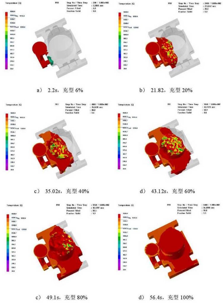
It can be seen from Fig. 1 that after the molten steel enters the mold from the inner gate, it basically moves forward in a fan-shaped manner. From the filling time interval, the time interval of filling 20% is 21.82s, 13.2s, 8.1s, 5.98s, 7.3s. It can be seen that the contact area between metal liquid and foam pattern is small at the beginning of the casting, and the influence of the theoretical pressure caused by the pyrolysis and gasification of the foam pattern leads to a slower filling speed in the early stage. In the middle and later stages, the contact area between the metal liquid and the foam pattern expands rapidly, and the filling speed increases gradually until the mold is filled. It takes 56.4 s for the liquid metal to fill the whole mold cavity, and the average pouring speed is 9 kg / S. in the middle and late filling period, the filling speed is fast, the horizontal soft moving distance is long, and there is no directional soft motion, which leads to the phenomenon of turbulence and softness in the front of the metal liquid.
Figure 2 shows the distribution diagram of solid increase rate at different times. The dark color refers to the unfrozen liquid metal, indicating the liquid increasing area; the light gray color refers to the solidified liquid metal, indicating the solid increase area.
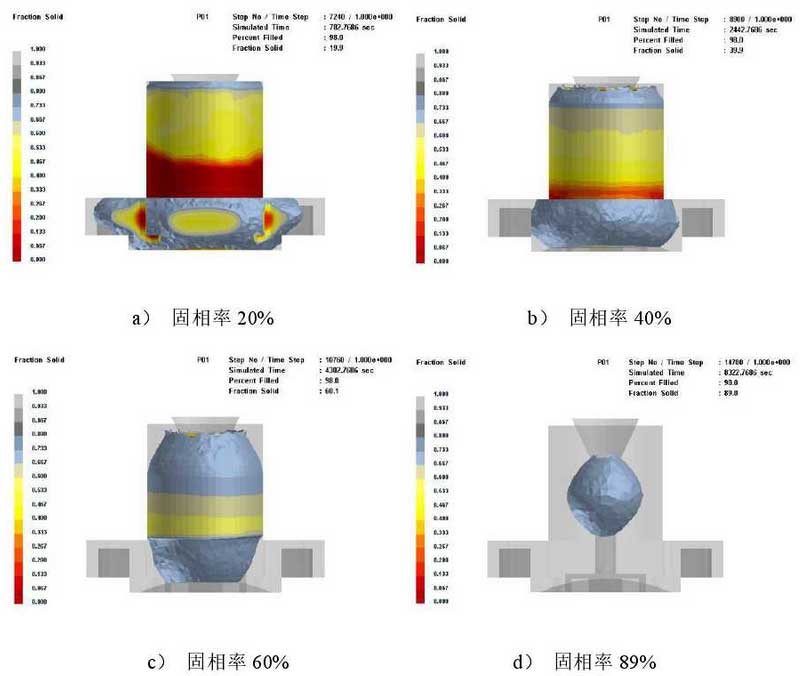
It can be seen from Fig. 2 that after filling the mold with liquid metal, the solidification starts from the thinner parts around the casting, and gradually solidifies to the casting center and riser, which basically conforms to the principle of sequential solidification. Due to the feeding effect of the riser, when the solidification ratio of the casting reaches 89%, all the liquid increasing areas are concentrated in the riser. During the whole solidification process, there is no isolated liquid increasing area in the casting, which indicates that the internal feeding condition of the casting is good.
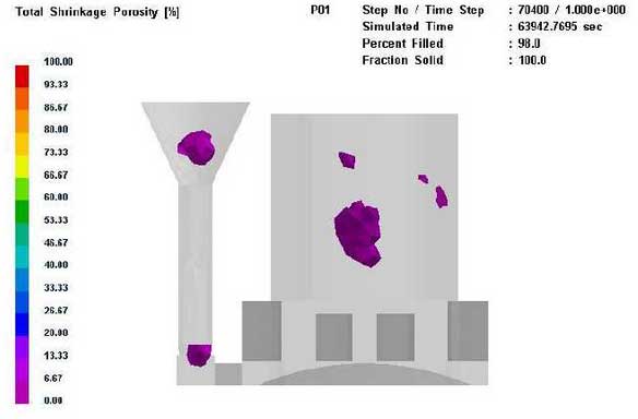
Figure 3 and Figure 4 show the prediction of shrinkage porosity when the porosity is greater than 3%.
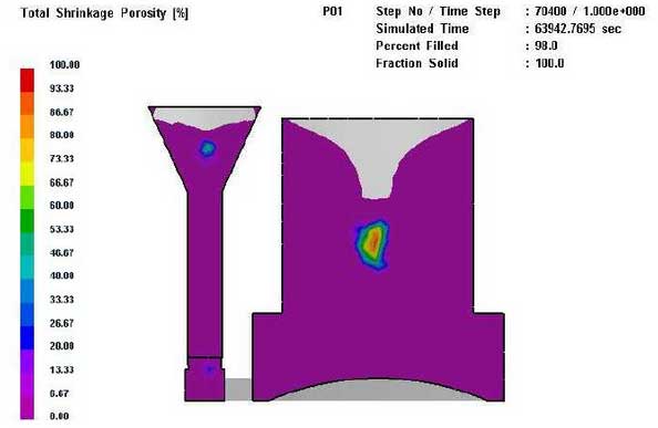
It can be seen from Fig. 3 and Fig. 4 that the shrinkage cavity and porosity are all concentrated in the pouring and riser, and the casting body group becomes denser, which is consistent with the situation predicted in Fig. 2.
The safety height of riser in Fig. 4 is measured by measuring tool of ProCAST software. It is known that the safe height of riser is about 7cm. According to the research of Huang Jin et al., the minimum safe height of cast steel riser is not less than 25% of the diameter of hot spot circle. When the diameter of hot spot circle of steel steel bearing is 13.5cm, the minimum safe height of riser is 3.4cm. However, 7cm is far beyond the minimum safe height, which means that the riser size can be further optimized to improve the process yield of castings.
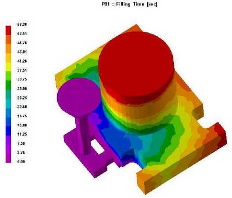
Fig. 5 shows the filling time nephogram and Fig. 6 shows the filling time slice diagram.
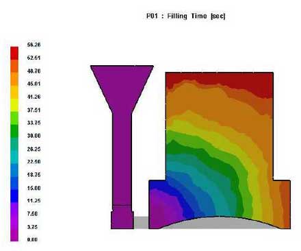
It can be seen from Fig. 5 and Fig. 6 that the filling time is gradually extended from the inner gate to the corner and riser of the casting far away from the inner gate, and the molten metal has been injected into the riser before filling the far end of the mold, which indicates that the riser does not fully play the role of slag collection and carbon removal during horizontal pouring. The horizontal soft moving distance of molten metal is long, especially from the corner area away from the gate. There is a large area of isolation in the process of pyrolysis, as shown in Fig. 7. In addition, due to the large temperature drop of the front edge of the liquid metal, the foam pattern of the isolated zone is not fully pyrolyzed, which easily leads to defects such as carburization, slag inclusion and porosity.