
① Analysis on the original pouring system of motor shell
See Fig. 1 for the original pouring system of motor housing. The two internal crossings of the top injection gating system are set at the column part with relatively thick sand casting, and multiple risers are set at the top, which leads to the heat concentration at the inner sprue part and the column top, which is basically the final cooling and solidification, so shrinkage cavity and shrinkage crack defects are easy to occur at this part. Secondly, the height from the inner sprue of the motor shell to the bottom of the sand mold is more than 600mm. When the high-temperature molten steel begins to flow into the cavity, it is directly washed at the bottom of the sand mold. Because the scouring force of the molten steel on the bottom of the sand mold is greater than the strength of the sand mold, sand washing occurs, and all the washed sand blocks or sand particles cannot float up into the riser, resulting in sand inclusion in the sand mold casting.
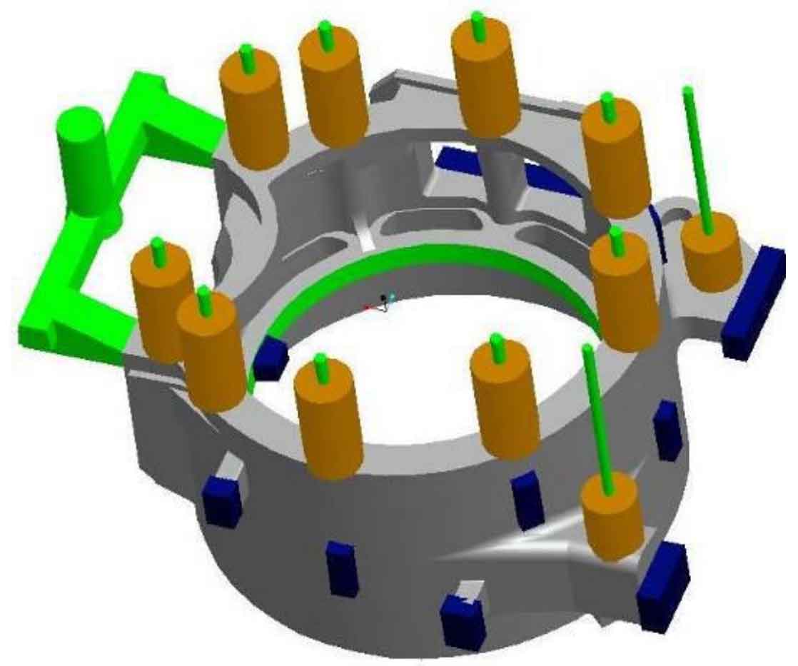
Finally, the sprue is made of furan resin sand. When the molten steel begins to enter the sprue, it is very easy to form sand flushing due to high temperature and large scouring force. The process of top injection gating system is not suitable for sand casting of motor shell.
② Design and analysis of bottom pouring system and riser of motor shell
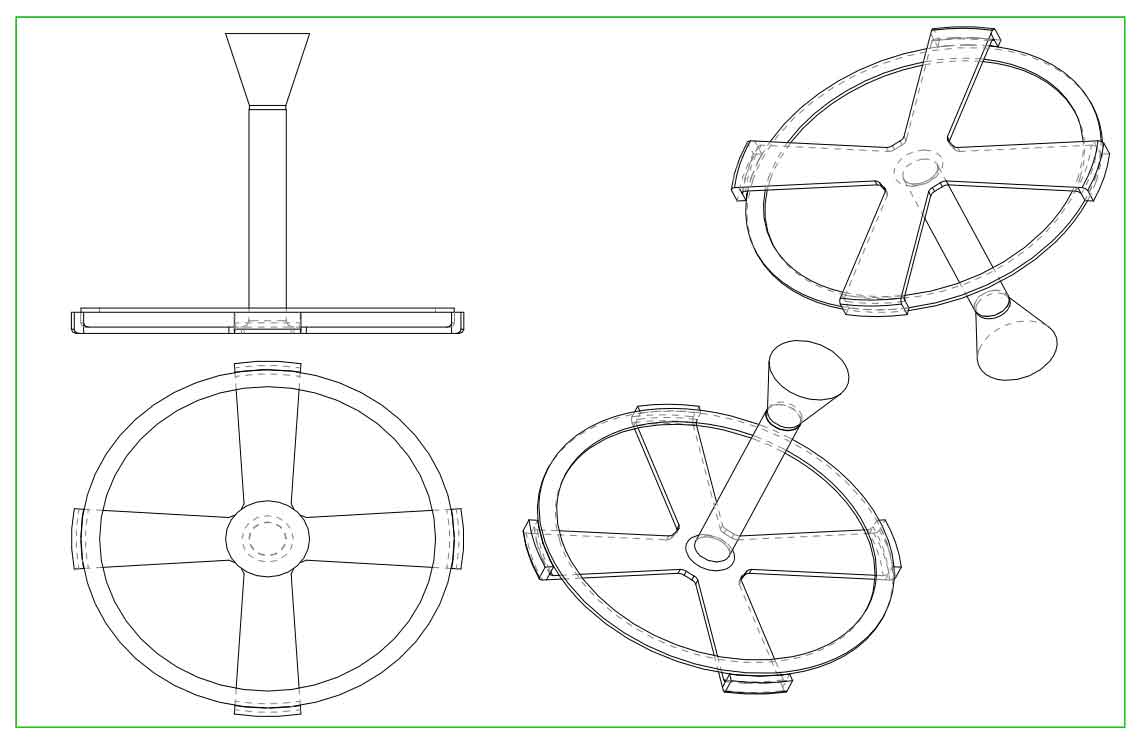
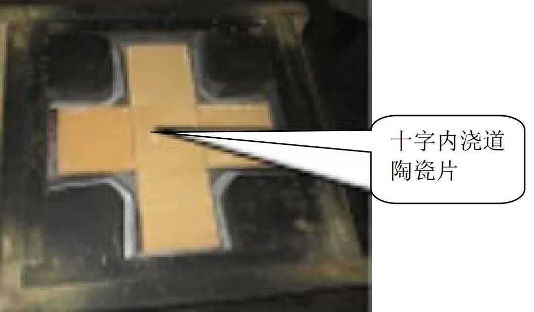
The top pouring process scheme of motor shell is redesigned into bottom pouring system, as shown in Fig. 2 and Fig. 3. The gate cup is made of ceramic gate cup, the sprue is made of ¢ 80 ceramic pipe, and the cross inner sprue is made of Yuzhu sand and ceramic sheet, as shown in Figure 4. Advantages of bottom pouring system:
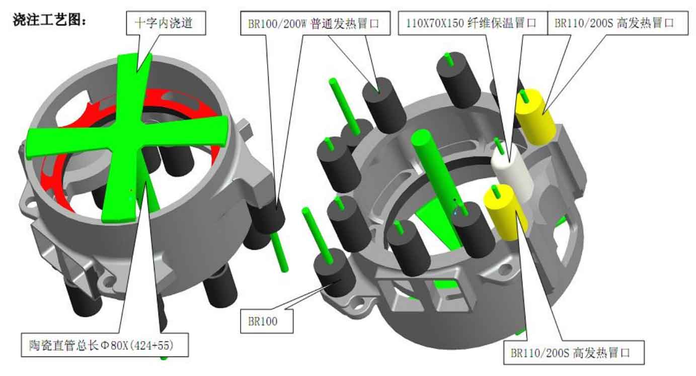
1) The cross ingate can effectively disperse heat and prevent excessive heat concentration at the ingate to form a large temperature gradient, resulting in tensile crack defects.
2) In the process of solidification and shrinkage of liquid steel, the cross inner sprue is equivalent to four tie bars, which can effectively prevent partial deformation of the barrel.
3) Ceramic sheet, ceramic pipe and ceramic gate cup are locally used in the gating system to prevent liquid steel from scouring the sprue and forming sand inclusion defects.
4) During the mold filling of the bottom pouring system, the flow of molten steel is relatively stable, which can effectively float the impurities, sand particles, gas and other harmful substances in the molten steel to the upper plane and riser, and reduce the occurrence of sand inclusion, pore and slag inclusion defects.
③ Riser design analysis
There are shrinkage porosity and shrinkage crack defects at the top of the column of the motor shell. The analysis shows that the internal sprue of the original process is set at this position to form a large hot spot and finally solidify. Due to the final solidification, the liquid steel is fed to other parts that solidify first. At this time, it needs a lot of molten steel to supplement itself. The height and diameter of the original design riser are too small, or even solidify first, so the feeding effect is not ideal. After calculation and analysis, the riser is designed from ordinary heating riser to high heating insulation riser. The diameter is changed from ¢ 100mm to ¢ 110mm. The riser height remains unchanged. See Figure 3 yellow riser