
0 Introduction
Casting crane is an important tool for extracting and dumping molten iron tanks in steel millsEquipment, due to its frequent operation in high temperature and dusty environments, willThe electrical control equipment and driving device are placed inside the main beam of the bridge and sealed tightlySeal and open inspection holes on the web plate of the main beam to facilitate the entry and exit of operatorsRepair equipment. In the 20th century, openings were generally made using a length as shown in Figure 1Square structure with R150 mm circular arc angle transition around to reduceLess stress concentration and the addition of reinforcement rings, due to the excessive procurement of steel by steel mills in China at that timeUsing open hearth steelmaking technology has relatively low efficiency and the frequency of crane use is not highHigh, so fatigue cracks rarely occur during actual use. howeverIn the 21st century, all of China’s steelmaking industry adopts converter steelmaking technology,Production efficiency has greatly improved, and the frequency of crane usage is also increasing,Especially during the period of 2003-2009, China’s steel industry flourishedDuring the glorious period, the feedback of cracking at the opening of the main beam web door was increasingThe more, this becomes the main factor restricting the design life of the main beam. Therefore, the needleIt is urgent to carry out fatigue calculations and structural improvements in this area.
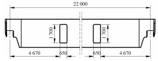
Figure 1 Main beam web plate door opening structure (mm)
After using a 210 ton casting crane in a steel plant for 5-6 years, it has been used in areas such asA fatigue crack appeared at the opening position of the web plate door of the main beam shown in Figure 2.Therefore, the load and operating rate experienced by the crane during the flipping operation are evaluatedConduct a detailed analysis to study the effect of the form and size of the perforated structure on the static strength of the main beamAnd the impact of fatigue strength.
1. Engineering Calculation Load
The main load borne by the main beam is the concentrated load generated by the wheels of the small carLoad, self weight, electrical control equipment, uniform load generated by the main beam platform, and largeThe horizontal inertial load generated when the car starts braking.
1) Concentrated load refers to the rated load of the crane and the self load of the trolley when fully loadedThe force acting heavily on the wheels of a small car. Due to the impact of small cars during lifting and operation, a lifting dynamic load coefficient is usually added in engineering φ 2. Running flushingCoefficient of impact φ Calculate with 4. It is known that the rated lifting capacity of the crane is 210 tons,The car weighs 90 tons and has 8 wheels, φ 2 and φ Take 1.17 and 4 respectively1. Then the dynamic load wheel pressure of the small car Pd=1.17 × 210 t+1 × 90 t2 ≈ 42 tons.

Figure 2 Photo of cracks at the opening of the web plate door of the main beam
2) Uniform load refers to the force acting on the entire span of the main beam, generallyThe weight of the main beam and the combined operation of the platform and electrical control equipment attached to itThe force generated by use. Due to the crane’s loading, unloading, or load descent controlWhen in motion, the self weight of the main beam will generate a pulsating force due to vibrationResponse. In engineering, an additional lifting impact coefficient is usually added φ 1 to calculate. Known,The main beam has a span of 22 meters, a self weight of 36 tons, a platform of 2.3 tons, and an electrical control equipment of 0.5 tons, φ oneIf 1.1 is taken, then the uniformly distributed load q=(36 t+2.3 t+0.5 t) × one point one22 m ≈ 1.94 t/m.
3) Horizontal inertial load refers to the lifting load when the crane crane is brakedThe horizontal force acting on the main beam due to inertia and self weight. Quality assurance in engineeringCalculate 1.5 times the product of quantity and operating acceleration. Given the running speed of the large vehicle80 m/min, using 1/4 drive, concentrated load and uniformly distributed loadThe horizontal inertial forces generated are PdH=1.5, respectively × forty-two × zero point two five ×Aunt 80/60 ≈ 18.2 t, qH=1.5 × one point nine four × zero point two five × Aunt 80/60 ≈0.84 t/m.
2. Strength analysis of main beams
2.1 Establishment of finite element model
Using SolidWorks software to create a three-dimensional solid for the main beamModeling, material Q355B. Due to the complexity of the main beam structure, in order to improveSimplify the detailed features that have little impact on the analysis results due to high operating speed, and remove process rounded corners, bevels, and other features on the parts. The S-N curve data of the main beam passing through multiple tables 1 Q345The block steel plate is welded and processed by fusion at the welding point,When conducting finite element modeling, consider it as an equal strength contact connection. rootAccording to the structural characteristics of the main beam, plate and shell elements are used for mesh division, totalingThere are 73485 units and 139692 nodes.
2.2 Static strength analysis
The car is a moving load on the main beam, when the car is located at 1/4 spanAt this time, this position is usually also the opening position of the web door and the fully loaded overturning position of the craneThe location of the homework package, where the normal stress and shear stress are equivalent, has a certain degree ofDanger. Using SolidWorks Simulation for finite element analysis,The stress results are shown in Figure 3. From Figure 3, it can be seen that the web door is openThe stress suddenly increases at the position of the hole, reaching a maximum of 152.24 MPa, while the surrounding areaThe stress is below 115 MPa.
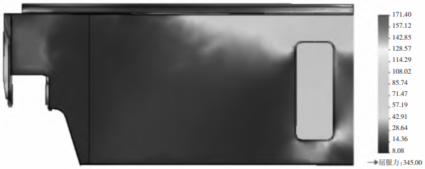
Figure 3 Stress of Main Beam (MPa) Diagram
2.3 Fatigue strength analysis
The main beam bears alternating loads, even if the stress does not reach strength failureLimit, but as the alternating load cycle reaches a certain number of times, it will also sproutCracks, fatigue damage occurs, making it unable to withstand the original load untilFatigue damage occurs, which is more covert and dangerous.In GB/T 3811-2008 “Design Specification for Cranes”, fatigue calculationThe stress ratio method has always been used. With the development of fatigue calculation theoryDevelopment, the US Highway Bridge Design Specification states that nominal stress is a determining factorThe main variable of fatigue strength for each type of rib plate construction detail changesThe traditional view in the academic community, and this conclusion has been adopted by many steel structuresUsed by the accounting department. The nominal stress method uses the S-N curve to reflect the material nameThe relationship between stress S and fatigue life N is expressed using the formula SmN=CTo represent.
2.3.1 Determination of S-N curve
Casting cranes, due to their high working level, are generally A7 orA8. During design and manufacturing, it is required to polish the welds in key areasThe concentration level of force is controlled at K2. Generally, when extracting and dumping steel ladlesFor fully loaded operations, the stress state level of the main beam is generally set to P4. rootAccording to GB/T 3811-2008 “Code for Design of Cranes” regarding fatigue gaugesAccording to the calculation regulations, the stress concentration level K2 connected by welded componentsThe basic value of fatigue allowable stress for the corresponding work levels E1-E8Establish S-N for the number of cycles corresponding to the stress level state P4 of the structural componentThe curve data is shown in Table 1.
2.3.2 Load spectrum at the web door
Transfer the ladle from the casting crane to the next ladle transfer asEstablish a load spectrum for the horizontal and vertical loads at the opening of the web door within one working cycle time domain, as shown in Figure 4Show. In Figure 4: A-B-C-D represents the crane transporting a full tank of steel ladleOpen to the front of the converter; D-E indicates that the crane flips over the converter molten ironPackage homework; E-F-G-H indicates that after the crane completes the flipping of the package, the empty tank will be emptiedTransport the ladle to the pouring pit.
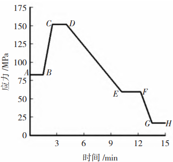
Figure 4 Stress time history at the opening of the web door
2.3.3 Analysis results
The fatigue life analysis results of the main beam are shown in Figure 5, with door openingsIn loop to 1.07 × 10⁵ times will result in fatigue failure, which is crucial for castingCrane construction generally adopts a three shift system, with 17 work cycles per shiftRing, excluding regular maintenance time, works approximately 350 days a year, which is one year1.75 × 104 working cycles. Based on this calculation, approximately 6 years later, the mainFatigue cracks will appear at the opening of the beam door, which is much lower than that of the casting craneA design lifespan of approximately 15-17 years.
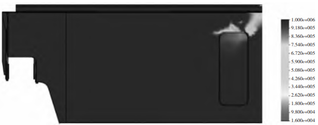
Figure 5 Fatigue life of the main beam (times)
3 Optimization of the opening of the web door
In order to improve the service life of the crane bridge, it is necessary to open the doorImprove the hole to align with the overall lifespan of the crane main beamConsistent.
3.1 Analysis of stress concentration at door openings
From the analysis results of static strength and fatigue strength, it can be seen that there is a sudden change in stress at the corner of the door opening. According to the theory of stress concentrationYes, for the Flat noodles bearing in-plane bending moment, open it on the center lineWhen using a rectangular hole as shown in Figure 6, a high pressure will be generated at point A on the edge of the holeConcentrated stress, its value is:
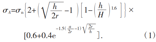
In the formula: σ A is the concentrated stress at point A; σ N is the reference stress of the web plate;H is the height of the main beam web plate; H is the height of the opening; A is the width of the opening; R isOpening fillet radius.
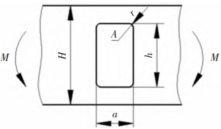
Fig. 6 Stress Concentration of Rectangular Hole in Flat noodles
3.2 Analysis of the Influence of Openings on Stress Concentration of Main Beams
From equation (1), it can be seen that the concentrated stress at point A is in the main beamUnder the condition of constant belly plate height, the height, width, andThe fillet radius is related. In engineering design, in order to reduce concentrationStress, generally adding reinforcement rings; In addition, holes are also made for easy operationPersonnel entering and exiting, usually with a hole width of 650 mm and a height of1 600~1 800 mm. In order to study the effect of openings on stress concentration in the main beamSound, with hole height and fillet radius as parameters, analyzed through finite element calculationThe variation law of concentrated stress under different combinations. Point A under each set of parametersThe stress situation is shown in Table 2.
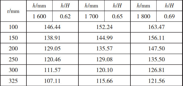
From Table 2, it can be seen that the concentrated stress at point A varies with the opening of the holeIt increases with the increase of height and decreases with the increase of fillet radius. WhenWhen the fillet radius is 325 mm, that is, when the hole type is a long elliptical hole, the concentrated stressThe minimum force.
3.3 Optimization of perforated structures
In engineering design, in order to reduce stress concentration, the circleThe angle should be as large as possible and the opening height should be as small as possible, but at the same time, in order to achieve fullThe minimum height required for foot structure design is 1600 mm, and the maximum height should not exceed 0.67H according to the reinforcement theory of equal moment of inertia of the reinforcement ring. As shown in Figure 7As shown, the door opening structure is changed to a long oval shape, and in order to reduce the openingConcentrate stress at the hole and arrange reinforcement ribs on the inner side of the web plate for reloadingAfterwards, static strength and fatigue strength analysis will be conducted to determine the stress reduction at the door openingAt 115.66 MPa, the fatigue life increased to 2.72 × 10⁵ times, approximately15.5 a, consistent with the design life of the main beam.
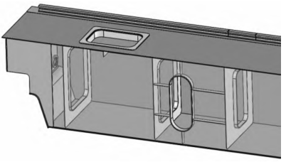
Figure 7: Improved structure of abdominal door opening
In addition, due to manufacturing errors in the opening of the belly plate and the reinforcement ring,It cannot be guaranteed that the opening and reinforcement ring will fully fit, and the method shown in Figure 8-2 should be usedWeld in the manner shown to avoid gaps between the web plate and reinforcement ringInternal stress caused by welding seam filling and requiring polishing of the welding seam to eliminate itExcept for residual stresses generated during the manufacturing process.
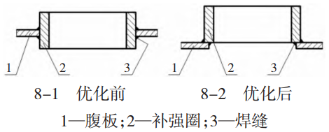
Figure 8 Welding method of reinforcement ring
4 Conclusion
As the foundation of the crane’s load-bearing capacity, the bridge determines the use of the craneService life. With the improvement of metallurgical technology, the use of casting cranesAs the frequency increases, fatigue life calculation becomes an urgent issue that needs to be addressedThe difficult problem. In addition, due to increasingly fierce market competition, cost control is alsoIt is an important factor in ensuring the winning bid of the project. In this context, it is required thatDesigners cannot rely solely on experience and cost to design, they mustUsing modern design methods for analysis and comparison, combined with one’s ownDesign experience is used for design optimization, so that the designed product can be improvedAffordable and more competitive in the market.