
The production of high-integrity, large-scale sand casting products presents significant challenges, particularly when the material is ductile iron and the component geometry is complex. This article details a comprehensive methodology for the process design and optimization of a massive ductile iron volute casing, demonstrating how systematic analysis and numerical simulation can converge to achieve a robust, cost-effective, and high-quality casting solution. The focus is on leveraging the inherent properties of ductile iron and the geometric features of the part to design a gating system that promotes uniform filling and solidification, ultimately enabling a riserless casting approach.
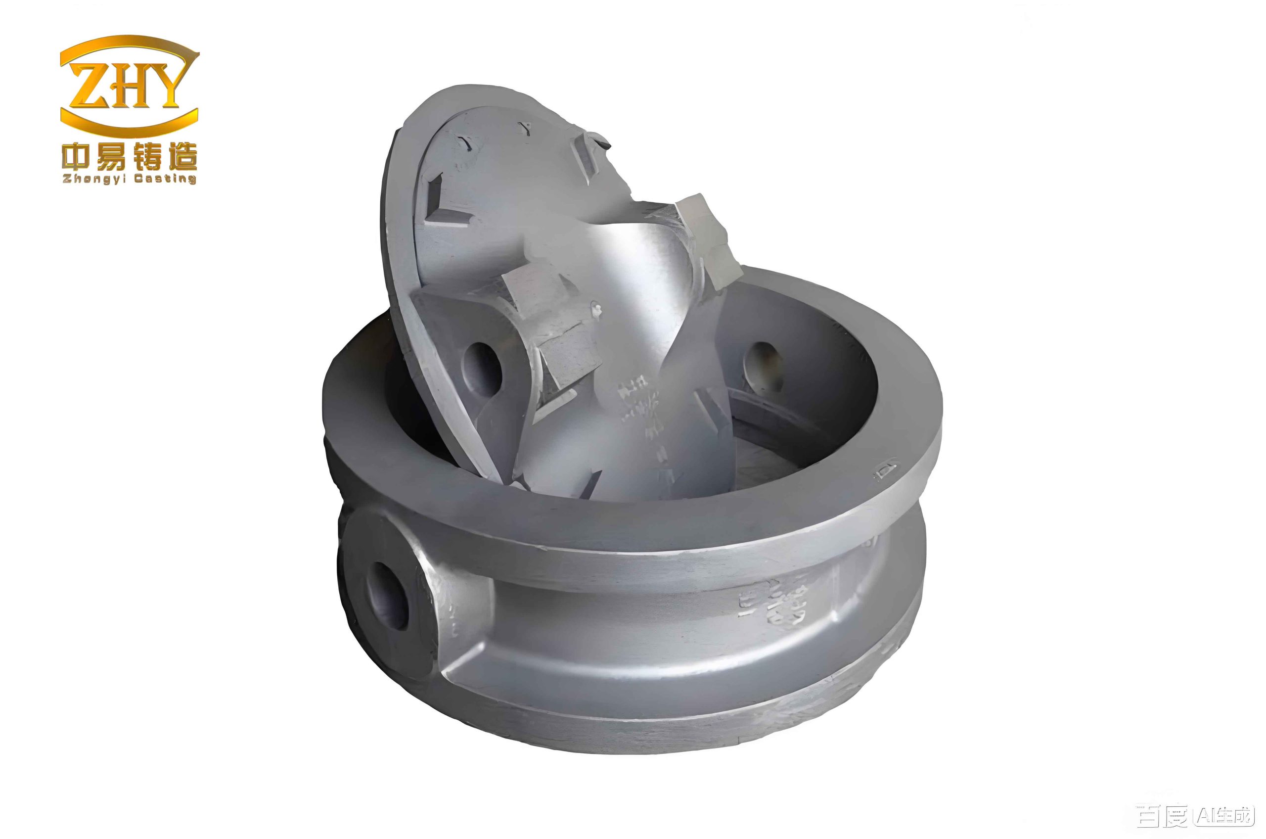
The subject component is a turbine volute casing with the material specification QT500-7. Its complex geometry, characterized by a spiral volute passage, poses specific challenges for liquid metal flow and solidification control. Key characteristics of this large sand casting product are summarized below:
| Parameter | Value |
|---|---|
| Material | Ductile Iron (QT500-7) |
| Overall Dimensions (L x W x H) | 1512 mm x 1385 mm x 814 mm |
| Approximate Weight | 1972 kg |
| Maximum Wall Thickness | 100 mm |
| Minimum Wall Thickness | 30 mm |
| Wall Thickness Ratio | ~3.33:1 |
| Primary Quality Requirement | Freedom from shrinkage, porosity, and sand inclusions. |
The significant variation in wall thickness is a critical concern. In ductile iron, large differences in section size lead to substantial variations in cooling rates, which can cause severe inhomogeneity in the graphite nodule formation (graphitization). This non-uniform microstructure directly compromises the mechanical properties and pressure tightness of the final sand casting product. Therefore, the primary objective of the casting process design is to minimize the thermal gradient during solidification.
Foundry Process Design Philosophy
The process was designed for low-volume production using self-setting resin sand molds, supported by strong flasks to withstand metallostatic pressure and graphite expansion forces. The design philosophy centered on two core principles inherent to ductile iron: 1) Utilizing fluid flow dynamics favorable to the volute geometry, and 2) Exploiting the graphite expansion phase for autonomous feeding (riserless casting).
1. Selection of Pouring Position and Parting Line
Two primary pouring orientations were analyzed. The first positioned the large volute face at the bottom. This was rejected due to the high risk of slag and gas entrapment in the critical large-diameter face, which also required a high surface finish (Ra 3.2). Furthermore, core support in this orientation would be complex, requiring multiple chaplets.
The chosen orientation positions the large planar face at the top and the volute opening downward. This offers several advantages for producing sound sand casting products:
- The critical volute face forms in the drag (lower mold half), ensuring better metal quality as lighter impurities float away from it.
- The core can be anchored securely from the bottom, eliminating the need for chaplets and simplifying molding.
- The parting line is placed at the largest cross-section of the volute, which is a plane, facilitating easy pattern withdrawal and mold assembly. A small side core is used for the tilted flange feature.
2. Gating System Design for Uniform Filling and Thermal Management
The gating system is the most crucial element for achieving the design goals. Conventional approaches, such as peripheral gating around the volute or bottom gating into the large opening, were evaluated and found suboptimal. They led to long flow paths, increased oxidation, turbulent filling, and complicated mold construction.
The innovative solution implemented involves placing the ingates at the thinnest section of the casting, specifically on both sides of the flange adjacent to the thin-walled “inclined pipe” section. The rationale and calculations behind this are multi-faceted:
A) Filling Dynamics: The spiral volute geometry naturally guides fluid flow. Metal enters the thin flange area and then flows smoothly along the volute channel in a naturally rising spiral. This promotes laminar, rapid, and uniform filling. The filling time ($t_f$) can be estimated using the basic fluid flow equation:
$$ t_f = \frac{V_{casting}}{\mu \cdot A_{choke} \cdot \sqrt{2gh}} $$
Where $V_{casting}$ is the casting volume, $\mu$ is the discharge coefficient, $A_{choke}$ is the choke area, $g$ is gravity, and $h$ is the effective sprue height. For this design, $t_f$ was targeted and achieved at approximately 36 seconds.
B) Thermal Gradient Minimization: Placing the ingates at the thinnest section acts as a thermal “trigger.” This area, with its high surface-area-to-volume ratio, will cool and solidify first. Meanwhile, the thick top section cools more slowly. By introducing hot metal at the fastest-cooling region, the temperature difference ($\Delta T$) between thick and thin sections is dramatically reduced. We can express the solidification time ($t_s$) for a section using Chvorinov’s rule:
$$ t_s = k \cdot \left( \frac{V}{A} \right)^n $$
Where $k$ is the mold constant, $V/A$ is the modulus, and $n$ is an exponent (~2 for sand). The goal is to make the solidification times of different sections as close as possible ($t_{s,thin} \approx t_{s,thick}$). Gating into the thin section helps balance the effective modulus during the initial cooling phase.
| Gating Scheme | Advantage | Disadvantage |
|---|---|---|
| Peripheral Gating | Distributes metal. | Long flow path, turbulence, oxidation. |
| Bottom Gating (Large Hole) | Quiet filling. | Complex 3-part mold, long flow path. |
| Proposed Thin-Section Gating | Minimizes thermal gradient, short path, uses natural volute flow. | Requires precise design. |
3. Achieving Riserless Casting through Controlled Solidification
Ductile iron undergoes a significant volume expansion (typically 4-6%) during the austenite-graphite eutectic reaction. This expansion can compensate for the earlier liquid and solidification shrinkage, making riserless casting feasible if the process is properly designed. The key conditions are:
- Early Ingate Solidification: The ingates must freeze before the casting sections they feed. This seals the casting and allows internal pressure from graphite expansion to build up, effectively “self-feeding” shrinkage. The thin-section gating naturally satisfies this condition.
- Strong, Rigid Mold: The mold must be strong enough to contain the expansion pressure without wall movement (mold wall shift). The use of resin sand with heavy, rigid flasks is critical here.
- Adequate Casting Modulus: The casting must have a sufficient geometric modulus to promote a favorable temperature gradient. The casting’s main body had a modulus of approximately 3.1 cm, which is suitable.
- Controlled Solidification Sequence: A directional solidification pattern must be established toward a designed “feed metal reservoir” or within the casting itself.
To enforce the correct solidification sequence and manage the heavy top section, several auxiliary measures were implemented:
- Chills: External chills (made of cast iron) were strategically placed at thermal centers and thick sections of the volute walls. Their function is to increase the local cooling rate, effectively reducing the local modulus and aligning its solidification time with thinner adjacent areas. The chill design can be related to the required heat extraction.
- Top Geometry Modification: The large top surface was designed with a slight conical taper (approx. 2°) rising toward the center. This provides an additional 15 mm of machining stock that also acts as a “sacrificial” zone for floating slag and gas, ensuring the integrity of the critical lower regions of the sand casting product.
- Atmospheric Venting: Small vent holes were placed in the top mold to allow air and gases to escape easily during pouring, preventing back-pressure and facilitating slag floatation into the tapered top region.
| Process Element | Function in Riserless Strategy |
|---|---|
| Thin-Section Gating | Triggers early solidification at ingates; seals system. |
| Resin Sand with Heavy Flasks | Provides rigid mold wall to contain expansion pressure. |
| Strategic Chills | Controls local solidification, minimizes isolated hot spots. |
| Tapered Top with Vents | Provides pressure relief and slag collection zone. |
4. Core and Mold Engineering
The internal volute cavity is formed by a single, large resin sand core. To manage its weight and ensure proper venting, the core was designed with hollow sections. It is anchored securely via core prints at the bottom of the mold (drag), eliminating buoyancy issues. The sprue was constructed using a ceramic tube to prevent erosion by the high-metal head over the extended pouring time, a common defect source in large sand casting products. A ceramic pouring cup and a sprue base well were used to further reduce turbulence and mold erosion at the metal entry point.
Numerical Simulation and Validation
The entire process was modeled and analyzed using advanced casting simulation software (AnyCasting) to validate the design before tooling manufacture. The simulation provided critical insights into filling patterns, solidification sequences, and potential defect formation.
Filling Analysis: The simulation confirmed the anticipated filling pattern. Metal entered symmetrically through the two ingates, filled the thin flange region, and then progressed smoothly and uniformly along the ascending spiral volute channel. The filling was completed in 36.5 seconds without visible turbulence, splash, or cold shuts. This laminar fill is essential for producing clean, defect-free sand casting products.
Solidification Analysis: The temperature gradient and solidification progression were visualized. The results showed that, aided by the strategic chills, the solidification fronts moved progressively from the thin walls and ingates toward the thicker sections and finally to the tapered top. The ingates solidified early, creating an isolated, sealed casting volume. Most importantly, no isolated liquid hot spots were observed in the main volute body, indicating a lack of macro-shrinkage conditions. The last area to solidify was the central, tapered portion of the top plate, which was designed as the feed and impurity reservoir.
Defect Prediction: The shrinkage porosity prediction module indicated a very low risk of shrinkage defects in the functional areas of the volute. Any predicted porosity was isolated to the feeder head (the tapered top) and the gating system itself, which are later removed. This confirmed the effectiveness of the riserless approach and thermal management for this specific sand casting product.
| Simulation Output | Observation | Conclusion |
|---|---|---|
| Filling Sequence | Smooth, laminar, spiral advancement from thin-section ingates. No turbulence. | Gating design successfully utilizes part geometry for optimal filling. |
| Solidification Pattern | Directional solidification from thin walls/ingates to thick top. Ingates freeze early. | Condition for pressure build-up and self-feeding is met. |
| Porosity Risk | No shrinkage in main casting. Minor porosity limited to top feeder zone. | Riserless strategy is validated. Top taper acts as effective safety reservoir. |
Conclusion and Principles for Large Ductile Iron Castings
This detailed analysis demonstrates a successful, optimized sand casting process for a large, complex ductile iron volute. The key outcomes and generalized principles for similar sand casting products are:
- Thermal Gradient Control is Paramount: For ductile iron with varying sections, gating into thinner areas can be more effective for homogenizing cooling than gating into thick areas. The goal is to balance the solidification times, as approximated by the modulus. Minimizing $\Delta T$ is directly linked to achieving uniform graphite microstructure.
- Exploit Natural Fluid Flow Paths: The geometry of the part itself can guide an optimal filling strategy. Designing the gating to align with natural flow channels (like the spiral volute) reduces turbulence and promotes a calm, rapid fill.
- Riserless Casting is a Systems Approach: It is not merely the absence of a riser. It requires the simultaneous fulfillment of multiple conditions: early ingate freezing ($t_{s,gate} < t_{s,casting}$), a high-strength mold cavity, a sufficient casting modulus, and a controlled solidification path. The pressure balance during expansion is critical and can be expressed conceptually as:
$$ P_{graphite-expansion} + P_{metallostatic} > P_{shrinkage} + P_{mold-deformation} $$
Where a rigid mold minimizes $P_{mold-deformation}$, allowing the internal pressure to overcome shrinkage. - Simulation is an Essential Verification Tool: Numerical simulation allows for the virtual testing of multiple scenarios, providing visual and quantitative proof of filling behavior, thermal gradients, and defect formation before committing to expensive tooling and trial casts. It transforms process design from an empirical art into a predictable engineering discipline.
This optimized process resulted in a casting methodology that facilitates easy molding and core setting, ensures uniform and rapid filling, promotes slag flotation to a designated area, and achieves sound material properties through controlled solidification. It represents an optimal balance between casting quality, material yield (no risers to remove), and production cost for this class of large, engineered sand casting products.