
The pursuit of perfection in metal casting is a continuous journey, balancing material science, fluid dynamics, and thermal management. As a foundry engineer, my primary focus is on the reliable and economical production of high-integrity sand casting products. The inherent flexibility of sand casting allows for the creation of components ranging from intricate brackets to massive machinery bases. However, this flexibility is coupled with the persistent challenge of internal defects such as shrinkage porosity and cavities, which compromise the mechanical performance of the final part. This article delves into a systematic methodology for process optimization, combining empirical analysis with advanced numerical simulation, to elevate the quality of sand casting products, using a specific component as a detailed case study to illustrate universal principles.
The landscape of modern manufacturing is populated by a vast array of sand casting products, each with unique geometrical and functional demands. The success of any casting process hinges on the controlled solidification of molten metal. Two fundamental principles guide this control: directional solidification and progressive solidification. Directional solidification aims to create a thermal gradient where the section farthest from the feed source solidifies first, ensuring a continuous liquid feed path to compensate for volumetric shrinkage. Progressive solidification, on the other hand, refers to the advancement of the solidification front from the mold walls inward. For defect-free sand casting products, especially those with varying section thicknesses, achieving a controlled directional solidification pattern is paramount.
Fundamental Defects in Sand Casting: A Thermodynamic View
The primary defects targeted in this optimization are shrinkage-related: macro-shrinkage cavities and micro-shrinkage porosity. These defects originate from the physical fact that most metals and alloys contract upon solidification and further during cooling to room temperature. If this volumetric contraction is not continuously fed with liquid metal, voids form within the casting. The tendency for a specific section to develop such a defect is fundamentally described by its solidification time and its position within the thermal hierarchy of the casting system.
The solidification time for a simple shape can be estimated using Chvorinov’s rule:
$$ t_s = B \left( \frac{V}{A} \right)^n $$
where \( t_s \) is the total solidification time, \( V \) is the volume of the casting, \( A \) is its surface area, \( n \) is an exponent (often taken as 2), and \( B \) is the mold constant. This highlights that sections with a high Volume-to-Surface Area (V/A) ratio, known as thermal centers or hot spots, will solidify last and are most prone to shrinkage defects. In complex sand casting products, these hot spots often occur at section intersections, such as where ribs meet a flange or a hub meets spokes.
| Defect Type | Primary Cause | Typical Location | Effect on Product |
|---|---|---|---|
| Shrinkage Cavity | Insufficient liquid feed during final solidification of a major hot spot. | Isolated thermal centers, top of heavy sections. | Large, macroscopic void; severe stress concentrator; often leads to catastrophic failure. |
| Micro-Porosity (Shrinkage) | Interdendritic feeding obstruction in the mushy zone; dissolved gas evolution. | Distributed in regions of pasty solidification, often near thermal centers. | Numerous microscopic voids; reduces effective load-bearing area and ductility; affects pressure tightness. |
| Gas Porosity | Entrapment of air or mold gases, or precipitation of dissolved hydrogen. | Random, often in upper sections or near mold surfaces. | Spherical or elongated pores; reduces mechanical properties and surface quality. |
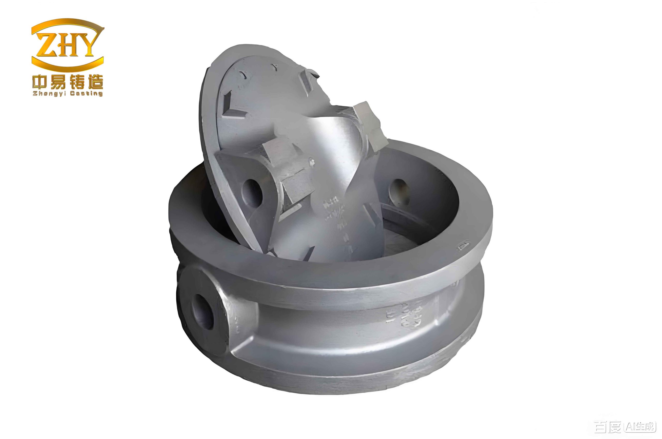
Case Analysis: The Handwheel Component
To translate theory into practice, I examined a representative component: a handwheel with a central hub, radiating spokes, and an outer rim. While seemingly simple, this geometry encapsulates the classic challenges found in many sand casting products: a thick hub acting as a dominant hot spot, thinner spokes, and a moderate-thickness rim. The initial production used a conventional side-gating system with the parting line along the wheel’s profile.
Initial Process and Observed Defect: The molten aluminum was introduced through a side gate into the spoke or rim area. Experimental castings consistently revealed shrinkage defects in the central hub. Metallographic analysis confirmed this was a shrinkage cavity, sometimes open to the surface, sometimes subsurface. This defect location immediately pointed to a failure in establishing proper directional solidification. The hub, with the largest V/A ratio, was the last to solidify, but the feeding path from the gating system was prematurely cut off as the thinner sections and the gates themselves solidified earlier.
Numerical Simulation as a Diagnostic Tool
To visualize the hidden solidification sequence, I employed finite element-based numerical simulation. The process involves solving the governing equations for fluid flow, heat transfer, and solidification. The key equation for heat transfer is the energy conservation equation, incorporating latent heat release:
$$ \rho C_p \frac{\partial T}{\partial t} = \nabla \cdot (k \nabla T) + \rho L \frac{\partial f_s}{\partial t} $$
where \( \rho \) is density, \( C_p \) is specific heat, \( T \) is temperature, \( t \) is time, \( k \) is thermal conductivity, \( L \) is latent heat, and \( f_s \) is the solid fraction.
The simulation of the initial side-gating scheme provided a stark visualization. The solid fraction plots over time clearly demonstrated the problematic sequence:
- The thin rim and spokes solidified rapidly.
- The gates and runners solidified shortly after.
- The central hub remained as a large, isolated liquid pool long after the feeding channels had frozen.
This created an isolated liquid zone with no source of feed metal, inevitably leading to internal shrinkage. The Niyama criterion, a local predictor for shrinkage porosity, is often used in such analyses:
$$ G / \sqrt{\dot{R}} $$
where \( G \) is the temperature gradient and \( \dot{R} \) is the cooling rate. Low values of this criterion indicate a high risk of microporosity formation, and the simulation confirmed a high-risk zone encompassing the entire hub section.
| Parameter | Initial Side-Gating Process | Optimized Top-Gating Process |
|---|---|---|
| Gating Position | Side (spoke/rim junction) | Top (center of hub) |
| Riser Function | Separate riser not used; gate provides minimal feeding. | Gating system acts as a live riser (integrated feed). |
| Solidification Sequence | Rim/Spokes → Gates → Hub (Problematic) | Rim → Spokes → Hub → Feeder (Ideal Directional) |
| Thermal Gradient Direction | Disorganized; hot spot isolated. | Vertical, from casting bottom upward into the feeder. |
| Predicted Defect Location | Central Hub | Top of the Feeder (sacrificial) |
| Process Yield | Higher (but with defective castings) | Slightly lower, but with near-100% sound castings. |
Integrated Process Optimization Strategy
The diagnostic phase clearly identified the root cause: the thermal and feeding pathways were misaligned. The optimization strategy needed to re-establish a clear, controlled directional solidification path terminating in a reservoir of liquid metal. For this class of axi-symmetric sand casting products with a central mass, the most effective solution often involves repositioning the casting and integrating the feeding system.
The Optimized Design: The wheel was inverted in the mold. The parting line was set at the wheel’s back face. A downsprue was connected directly to the top of the central hub, which now became the bottom of the mold cavity during pouring. This sprue was sized to have a solidification time greater than that of the hub itself, effectively turning it into a “live” or “top” riser. The governing principle for riser sizing can be summarized by the feeding demand equation. The riser must compensate for the shrinkage in the casting section it feeds:
$$ V_r \geq \frac{V_c \cdot \beta}{\eta} $$
where \( V_r \) is the required riser volume, \( V_c \) is the volume of the casting region fed, \( \beta \) is the volumetric shrinkage of the alloy (typically 3.5-6.5% for Al-Si alloys), and \( \eta \) is the feeding efficiency of the riser (typically 10-30% for sand castings, accounting for heat loss).
Simulation of this optimized design showed a transformed solidification pattern. The freezing front now progressed uniformly from the outer rim, through the spokes, into the hub, and finally up into the vertical feeder/sprue. The last point to solidify was unequivocally within the feeder neck, which is designed to be removed, thus pulling any potential shrinkage defect out of the functional sand casting product.
Practical Implementation and Compensatory Measures for Integrated Systems
While the integrated gating/riser system offers significant metallurgical advantages for producing sound sand casting products, it introduces specific practical challenges that must be addressed.
1. Slag and Oxide Entrapment: A top-pouring system loses the slag-trapping benefit of a well-designed bottom or tangential gating system. Turbulence can draw oxides into the mold cavity. Mitigation strategies are critical:
- Pouring Basin Design: Use a basin that maintains a consistent metal head and promotes quiescent flow into the sprue.
- Ceramic Filters: Installing a ceramic foam or mesh filter at the base of the sprue is highly effective in trapping non-metallic inclusions.
- Careful Pouring Practice: Maintaining a continuous, non-turbulent pour and keeping the sprue full to prevent vortex formation.
2. Mold Gas Venting: With metal entering from the top and the hottest metal (in the feeder) at the highest point, the displacement of air and binder gases from the deep mold cavity becomes more challenging. Inadequate venting can lead to back-pressure and gas porosity. Solutions include:
- Strategic Venting: Placing permeable vent rods or creating vent channels at the highest points of the cavity, particularly in blind pockets or opposite the ingate.
- Permeable Molds: Ensuring the sand mold has adequate permeability through proper sand compaction and binder content.
3. Erosion of the Mold Cavity: The high vertical drop of molten metal directly onto the hub surface can cause mold wall erosion, leading to sand inclusions. This is mitigated by:
- Reducer/Spread Core: Placing a small sand core or a ceramic insert at the point where the sprue meets the casting to spread the impact and reduce velocity.
- Optimized Sprue Design: Tapering the sprue correctly to maintain a choke and control velocity.
Generalized Framework for Optimizing Sand Casting Products
The lessons learned from this specific component can be abstracted into a general framework for optimizing a wide range of sand casting products. This framework is iterative and combines simulation with empirical validation.
Step 1: Geometrical and Thermal Analysis. Identify all thermal modules (sections with different V/A ratios). Calculate or estimate their relative solidification times. The hot spots are the modules with the longest \( t_s \).
Step 2: Feed Path Design. Define the desired directional solidification path. It should start from the geometrically farthest or thinnest sections and terminate at a designed feed source (riser). The feed path must remain liquid longer than the section it is feeding. The feeding distance for a section can be limited by the geometry; for a plate, the effective feeding distance \( L_f \) from a riser is often approximated as:
$$ L_f \approx 4.5 \cdot T $$
where \( T \) is the plate thickness. Chunks or heavy bosses require their own dedicated feeders.
Step 3: Gating and Riser Integration. Design the gating system to achieve the desired fill pattern with minimal turbulence. Whenever possible, position risers to leverage gravity feeding. For parts like the handwheel, integrating the sprue and riser is efficient. For larger or more complex sand casting products, a network of side risers, top risers, and chills may be necessary.
Step 4: Numerical Simulation and Iteration. Use simulation software to virtually test the design. Analyze fill patterns for turbulence, and most critically, analyze the solidification sequence and shrinkage prediction (using criteria like Niyama). Iteratively modify riser sizes, placement, and chill application until the simulation shows a sound casting with defects relegated to the risers.
Step 5: Prototype and Validation. Produce a limited run of castings using the optimized design. Conduct non-destructive testing (X-ray, ultrasound) and destructive sectioning to validate the absence of internal defects. Compare mechanical properties with specification requirements.
Conclusion: A Synergistic Approach to Quality
The production of high-quality sand casting products is an engineering discipline that has been profoundly enhanced by digital tools. The case of the handwheel demonstrates that a defect often perceived as a material failure is, in fact, a process design failure. By fundamentally understanding the physics of solidification and feeding, and by employing numerical simulation as a powerful diagnostic and predictive tool, foundry engineers can systematically de-risk the casting process. The optimized integrated feeder system is a testament to elegant engineering—turning a problem (the need for a feeder) into a solution by re-purposing an existing system element (the sprue). This approach, blending classical foundry principles with modern computational analysis, is the cornerstone for achieving dimensional precision, structural integrity, and reliability in the diverse and essential world of sand casting products. The final measure of success is not just a sound casting, but a robust, repeatable, and economical process capable of delivering consistent quality batch after batch.