
Within the aluminum electrolysis industry, the anode steel claw is a critical component. It forms an integral part of the rodding assembly, connecting the carbon anode block to the aluminum conductor rod via a cast iron collar. Its primary functions are mechanical support and efficient electrical conduction throughout the long potline cycle. Therefore, the material, typically ZG230-450 cast steel, must exhibit excellent electrical conductivity and sufficient mechanical strength. Beyond meeting the standard material specifications, the final casting must adhere to stringent dimensional tolerances (e.g., height deviation ≤ 2mm, claw head diameter deviation ≤ 1mm) and possess a flawless surface finish, free from defects like sand inclusions, cracks, slag, and porosity.
Traditionally, the majority of domestic producers have relied on sand casting for manufacturing these claws. While techniques like two-part molding and vertical sequential pouring have been employed to improve quality, inherent limitations of sand casting persist. These include relatively poor dimensional accuracy, high surface roughness, potential for lower material density and mechanical properties, and the necessity for extensive post-casting finishing (grinding). These factors collectively increase production costs, extend lead times, and introduce significant dimensional variability.
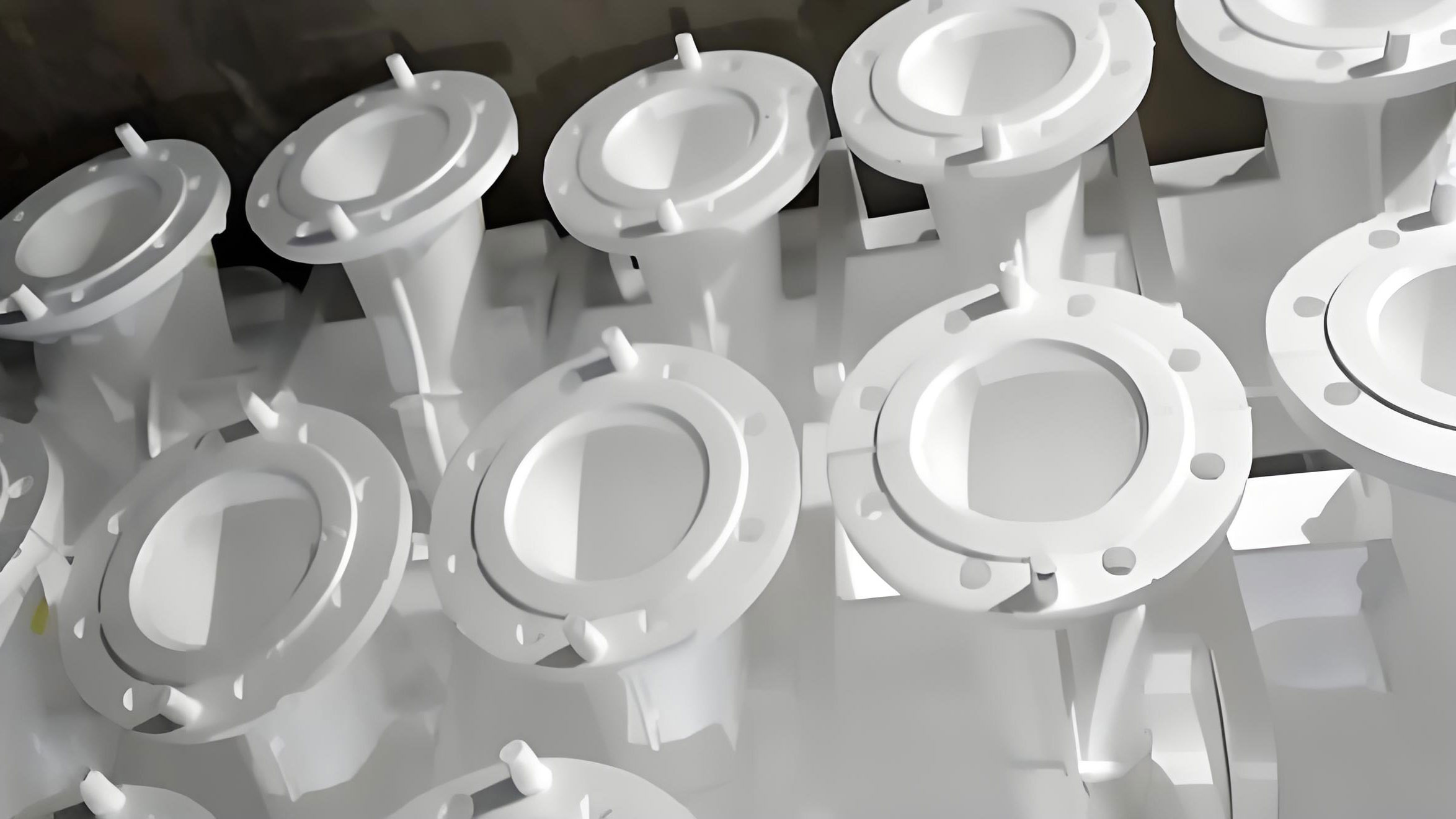
To overcome these challenges, our facility adopted the lost foam casting (LFC) process for anode steel claw production. Also known as evaporative pattern casting, LFC is a precision casting method that utilizes an expandable polystyrene (EPS) foam pattern. The pattern, coated with a refractory slurry and dried, is placed in a flask and surrounded by unbonded, dry sand, which is compacted via vibration. The mold requires no cores, binders, or parting lines. Molten metal is then poured into the mold under a controlled vacuum, causing the foam pattern to pyrolyze and be replaced by the metal. After a specified holding time, a near-net-shape casting is obtained. Compared to conventional sand casting, the lost foam casting process offers distinct advantages: simplified overall process flow, superior dimensional accuracy, and excellent surface finish, significantly reducing the need for secondary machining.
Analysis of the Initial Lost Foam Casting Process
Our original lost foam casting process for the steel claw employed a bottom-gating system with spherical feeders positioned at each of the four claw heads, as conceptually illustrated in the original technical documentation. This bottom-gating approach facilitates a progressive, layer-by-layer gasification of the foam pattern during metal pouring, promoting stable mold filling. The pyrolysis products tend to float upward, away from critical sections of the claw, thereby minimizing the risk of internal slag inclusions and gas porosity within the casting. Furthermore, the gases generated at the advancing metal front help to stabilize the unbonded sand mold walls.
The design of the gating system followed established hydraulic principles. The total cross-sectional area of the ingates was calculated using the formula:
$$\sum F_{gate} = \frac{G}{\mu t \sqrt{0.31 H_P}} \quad \text{(cm}^2\text{)}$$
where:
- $\sum F_{gate}$ is the total cross-sectional area of all ingates.
- $G$ is the total weight of molten metal passing through the ingates (casting weight + gating system weight + feeder weight), in kg.
- $\mu$ is the flow coefficient, typically 0.3–0.5 for steel castings.
- $H_P$ is the effective metallostatic pressure head, in mm.
- $t$ is the pouring time, in seconds, calculated as: $$t = c \sqrt{G}$$
The constant $c$ is determined from the relative density of the casting ($K_V$), which is given by:
$$K_V = \frac{G}{V}$$
where $V$ is the volume of the casting. The value of $c$ corresponding to $K_V$ is obtained from standard reference tables.
Once the ingate area was determined, the dimensions of the runner and sprue were sized based on standard proportional ratios for gating systems in lost foam casting:
$$\sum F_{gate} : \sum F_{runner} : \sum F_{sprue} = 1 : 1.1 : 1.2$$
For our specific claw design, this yielded the following approximate dimensions: Ingate: 40mm × 40mm; Runner: 45mm × 45mm; Sprue: 50mm × 50mm.
The spherical feeders served multiple critical functions: supplying liquid metal to compensate for solidification shrinkage, helping to control the thermal gradient, and acting as reservoirs to collect slag and allow for the escape of gaseous decomposition products. The spherical shape is advantageous in lost foam casting because, for a given volume, it has the smallest surface area, leading to the longest solidification time and thus optimal feeding efficiency. They can be easily fabricated and strategically placed.
However, this initial process scheme, while functional, presented several practical drawbacks. The complex gating arrangement with four separate feeders made pattern assembly, coating, and flask filling more labor-intensive. The extensive feeder necks and runners resulted in a high yield loss, as a significant portion of the poured metal had to be cut off and remelted. Furthermore, the need to machine the top surface of all four claw heads and the upper platform of the claw body (five surfaces total) imposed considerable mechanical processing costs and complexity. Occasional carbon defects on the upper surfaces of the castings were also noted. These issues motivated a comprehensive review and optimization of the gating and feeding strategy within the lost foam casting framework.
Proposed Optimization: Top-Gating with a Central Feeder
The optimized lost foam casting process proposes a radical shift to a top-gating system, consolidating the feeder and gating inlet onto the upper platform of the steel claw, as shown in the optimized scheme. Top-gating in lost foam casting is often approached with caution due to several inherent challenges. It can lead to turbulent metal flow, which for tall or complex patterns increases the risk of mold erosion and collapse (veining or scabbing). Perhaps more critically, the downward flow of metal is counter to the natural upward escape path of the foam’s pyrolysis gases, potentially trapping them and creating gas porosity or slag defects in the lower sections of the casting.
Despite these risks, the top-gating system offers compelling potential benefits that warranted investigation:
- Simplified Pattern Assembly: A single, central down-sprue attached to the platform drastically simplifies the foam pattern cluster, making coating, handling, and sand filling more efficient and less prone to damage.
- Enhanced Thermal Gradient: Metal enters from the top, meaning the upper sections of the casting (the platform and feeder) remain hottest the longest. This promotes a classic directional solidification pattern from the claw tips upward toward the feeder, which is ideal for soundness.
- Improved Yield: Eliminating the four individual claw-head feeders and their associated runners significantly reduces the total gating system mass, thereby increasing the casting yield (ratio of finished casting weight to total metal poured).
- Reduced Machining: With the feeder now situated on the platform, only the platform’s top surface requires machining (one surface instead of five), slashing machining time and cost. The sprue/feeder cutting operation is also simplified and less consumptive.
The central question was whether, through careful control of other process parameters, the disadvantages of top-gating in lost foam casting could be mitigated to produce a sound, high-quality anode claw. A comparative summary of the two approaches is presented below.
| Feature | Initial Process (Bottom-Gated) | Optimized Process (Top-Gated) |
|---|---|---|
| Gating Method | Bottom-gating via four ingates at claw heads. | Top-gating via a central sprue on the upper platform. |
| Feeder Location | Four spherical feeders, one at each claw head. | One large feeder/sprue combined on the upper platform. |
| Filling Behavior | Progressive, stable filling. Minimal turbulence. | Potentially turbulent. Requires careful parameter control. |
| Thermal Gradient | Controlled by feeder placement. Must be carefully balanced. | Naturally promotes directional solidification from claws up to the feeder. |
| Gas/Slag Escape | Favorable; gases escape upward away from metal front. | Challenging; gas escape counter to metal flow. Relies on vacuum and coating permeability. |
| Pattern Complexity | High. Multiple joints and delicate sections. | Low. Simple, robust cluster. |
| Calculated Yield | Lower (approximately 67.57%). | Higher (approximately 86.21%). |
| Post-Casting Machining | Five surfaces (4 claw heads + platform). High cost. | One surface (platform only). Low cost. |
Experimental Validation and Process Implementation
The feasibility of the optimized lost foam casting process was validated through a full-scale production trial. The LFC process is broadly divided into two operational areas: the “white area” (pattern making) and the “black area” (mold preparation, pouring, and finishing).
Pattern Manufacturing (White Area)
The claw pattern was produced from expandable polystyrene (EPS) beads. The beads were first pre-expanded in a pre-foamer to achieve a target bulk density and then aged in a storage silo to stabilize internal pressure. The conditioned beads were then blown into a multi-cavity aluminum tool (die) where steam heat caused them to fully expand and fuse, forming the precise foam replica of the steel claw. The gating system (sprue/feeder) was separately cut from foam board using a hot wire and then adhesively bonded to the claw pattern’s upper platform. This optimized cluster is significantly simpler and sturdier than the previous four-gate design.
Coating Application and Drying
A water-based refractory coating is essential in lost foam casting. It provides a barrier between the molten metal and the sand, helps manage foam gasification products, and imparts surface finish to the casting. Our coating formulation was primarily based on refractory fillers like zircon flour and silica flour, with additives for suspension, rheology control, and gas permeability. The assembled foam cluster was dipped into the coating slurry, ensuring complete coverage, with brush touch-ups in complex areas. The coating was applied in three layers to achieve a total dry thickness ≥ 3mm. The fully coated pattern was then dried in a controlled oven at 40–60°C to remove all moisture, resulting in a robust, handleable model with a total weight exceeding 6kg.
Mold Preparation and Pouring (Black Area)
Molding: We utilize high-quality, rounded ceramic sand (often called “proppant” or “bead sand”) for molding. This sand flows exceptionally well, provides excellent permeability for gas evacuation, and minimizes metal penetration, contributing to the superior surface finish. For a casting weighing approximately 500kg, a minimum mold wall thickness (sand fill around the pattern) of 150mm was maintained. The coated pattern was placed in a vented flask, and dry sand was filled around it while the flask was subjected to systematic vibration to ensure uniform and adequate compaction, especially under the claw heads, the horizontal beam, and the feeder neck.
Pouring Practice: The pouring operation is critical in lost foam casting. A steady, non-interrupted pour is mandatory to maintain the replacement front and prevent cold shuts. The flask is connected to a vacuum system during pouring and for a period afterwards. The vacuum serves multiple purposes: it draws the pyrolysis gases through the coating and the permeable sand mold, helps compact the sand around the evolving metal shape, and can improve metal feeding. The vacuum level must be carefully controlled; too low (<0.03 MPa) risks mold collapse, while too high (>0.05 MPa) can cause severe metal penetration into the sand. For our trials, the vacuum was maintained within the optimal range of 0.03–0.05 MPa (300–500 mbar). The molten ZG230-450 steel was poured at a temperature carefully calibrated for the section thickness and the thermal mass of the foam cluster.
Results, Analysis, and Discussion
The castings produced using the optimized top-gated lost foam casting process were successfully extracted from the mold after cooling. Visual inspection revealed a casting with a very smooth surface finish, free from the major defects commonly associated with poor top-gating, such as massive slag inclusions or gross porosity in the lower sections. A quantitative and qualitative comparison confirms the advantages of the optimized process.
Quantitative Improvement in Yield and Efficiency
The most immediate benefit was the dramatic increase in process yield. The yield is calculated as:
$$\text{Yield} = \frac{\text{Weight of Finished Casting}}{\text{Total Weight of Metal Poured}} \times 100\%$$
For the initial bottom-gated process, the extensive gating and feeding system resulted in a yield of approximately 67.57%. The optimized top-gated process, with its consolidated and minimal gating, achieved a yield of approximately 86.21%. This represents an increase of 18.64 percentage points, translating directly into significant material savings and reduced melting energy per usable casting.
Reduction in Post-Casting Processing
The reduction in required machining operations is profound. The initial process necessitated machining the top surface of all four claw heads and the upper platform. The optimized casting requires machining only the single upper platform surface where the feeder was attached. This simplifies fixturing, reduces machine tool time by over 80%, and lowers consumable tooling costs. Furthermore, the volume of metal to be removed via oxy-acetylene cutting for feeder removal is drastically reduced, saving on gas consumption and labor time.
Discussion on Mitigating Top-Gating Risks in Lost Foam Casting
The successful outcome of the trials indicates that the potential pitfalls of top-gating in lost foam casting can be effectively managed. Several factors contributed to this:
- Coating Permeability and Drying: The multi-layer, highly permeable coating was crucial. It allowed the rapid evacuation of foam pyrolysis gases downward and laterally through the coating into the sand, even against the metal flow, minimizing gas entrapment.
- Precise Vacuum Control: The applied vacuum actively pulled gases through the system, preventing a buildup of back-pressure that could force gases into the liquid metal. It also stabilized the sand mold during the potentially more turbulent initial fill.
- Pattern and Gating Design: The single, large-diameter sprue/feeder acted as an effective pressure head and provided a direct escape route for gases rising from the claw body during the final stages of fill.
- Metal Quality and Pouring Technique: Using clean, properly deoxidized steel and a swift, consistent pour minimized the generation of additional oxides and helped maintain a clean metal front.
The thermal benefits of top-gating were clearly realized. Solidification proceeded from the claw tips (farthest from the heat source) upward toward the massive thermal mass of the feeder on the platform, ensuring adequate feeding and soundness throughout the critical stress-bearing sections of the claw.
Conclusion
This investigation demonstrates that a significant optimization of the lost foam casting process for anode steel claws is not only feasible but highly advantageous. By transitioning from a conventional bottom-gated, multi-feeder system to a simplified top-gated system with a consolidated feeder on the claw platform, several key objectives were achieved:
- The fundamental viability of a top-gating approach for this specific geometry in lost foam casting was successfully validated, provided that supporting process parameters (coating, vacuum, pouring practice) are rigorously controlled.
- The process simplification led to tangible economic benefits: a marked increase in casting yield from ~68% to ~86%, and a drastic reduction in post-casting machining and cutting operations.
- These improvements collectively enhance production efficiency, lower unit manufacturing costs, and strengthen the competitive position of utilizing the lost foam casting process for high-precision, high-value cast components like the anode steel claw. This optimized methodology can serve as a valuable reference for similar castings produced via the lost foam casting technique.