
From the analysis of key technical problems, it can be seen that the composite squeeze casting die for large parts not only has the relevant functions of ordinary squeeze casting die, but also must solve the problems of pre closing, increasing the effect of extrusion force and quantitative mold filling. Therefore, a new die structure is set on the basis of the existing floating die, which can be called the floating rigid support die structure. Based on the design of large aluminum wheel hub, the forming die is designed according to the forming characteristics of composite squeeze casting of large parts, but the structure of the die is also applicable to other large parts suitable for composite squeeze casting.
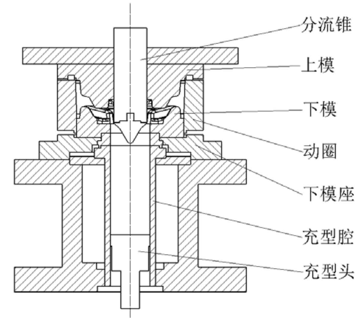
The floating die structure is shown in Figure 1. Its working principle is that the lower die is divided into two parts: the lower die seat and the moving ring. After the molten metal is transported to the filling device, the filling head presses it into the die cavity. The upper die down to squeeze the molten metal. At the same time, the moving ring is extruded to follow the upper die down. During the descending process of the moving coil, certain friction and pressure are generated on the molten metal to achieve the effect of grain refinement. At the same time, the lower die moves relative to the moving coil and also participates in the extrusion process. The existing floating die mainly adopts the floating mode of elastic support, that is, multiple springs are used to support the moving coil. This method compresses the support spring when the upper die squeezes the moving coil. When the upper die squeezes the pressure off, the reaction of the spring makes the moving coil return to its original position.
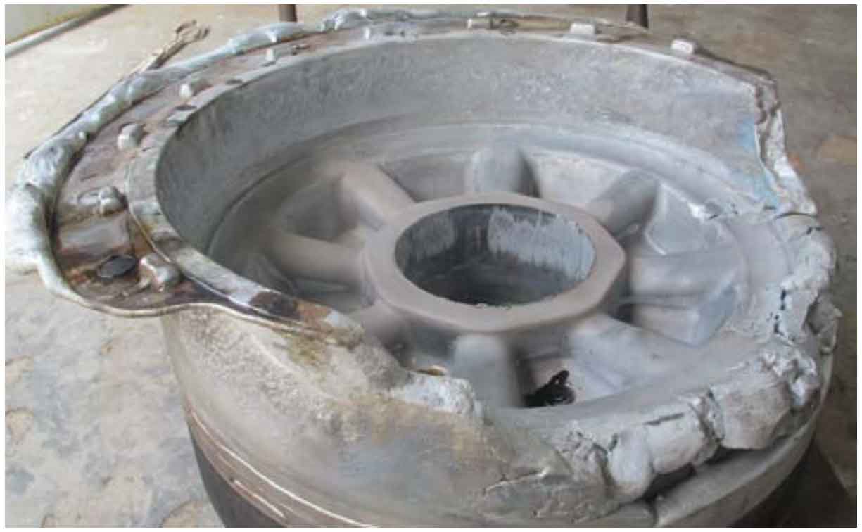
However, in the extrusion process of large parts with floating die supported by elasticity, a considerable proportion of castings will lack metal melt in some areas and overflow too much metal melt in some areas, as shown in Figure 2.
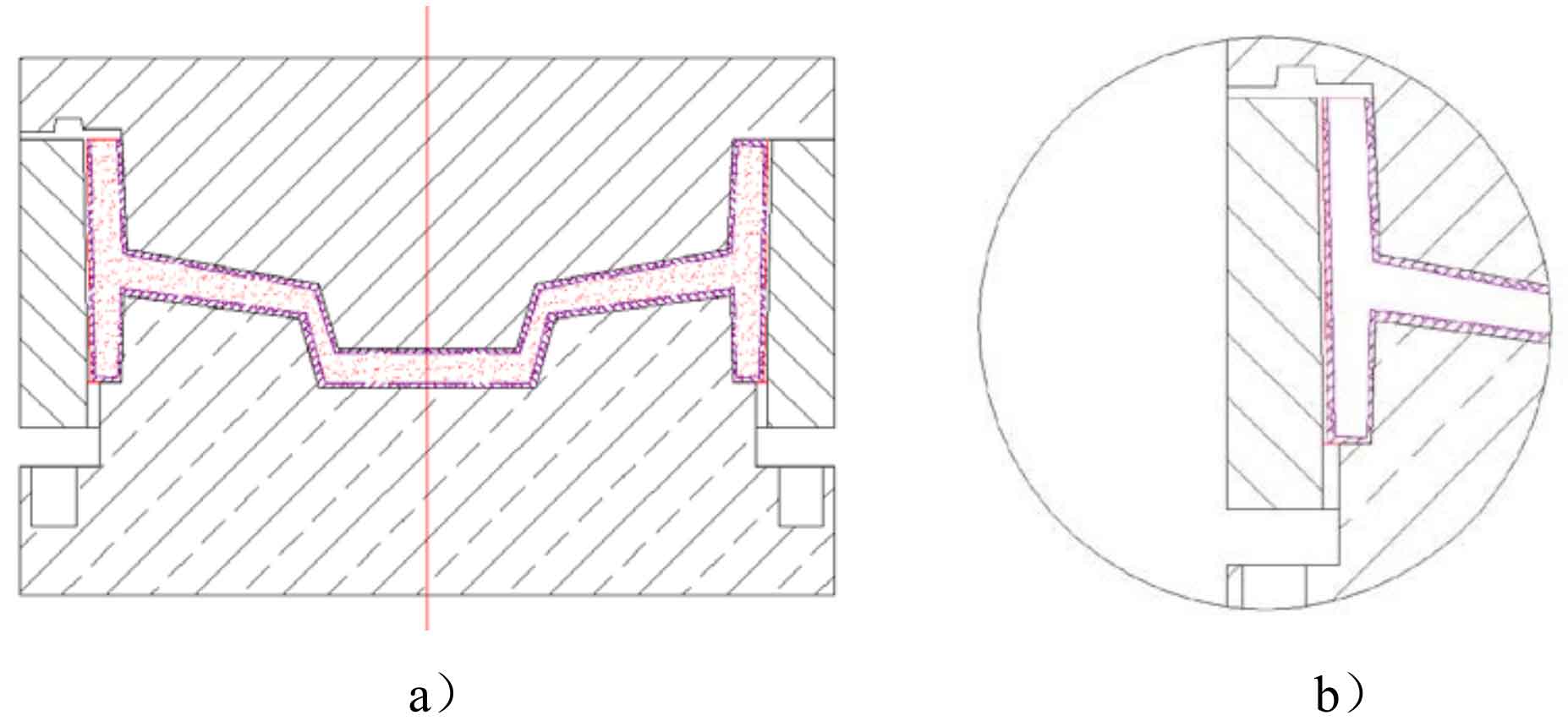
The cause analysis of this situation is as follows: after the metal melt fills the cavity, a layer of hard shell will be formed on the inner wall of the moving coil and the part where the upper mold contacts the metal melt. However, at the part where the upper mold is provided with an overflow groove, the metal melt has not formed a hard shell yet, with a flowing gap, as shown in Figure 3. When the upper die is extruded downward, the pressure exerted by the upper die is mainly concentrated in the hard shell layer. At this time, the isostatic pressure of the liquid metal melt is zero, and the metal melt shrinks due to solidification.
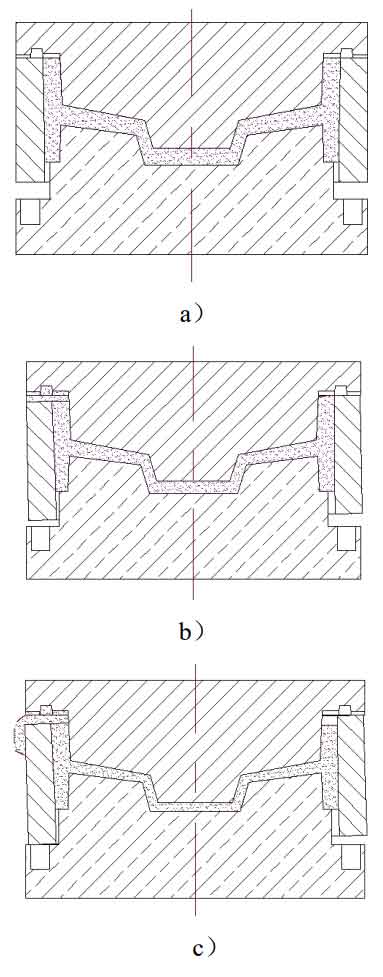
The upper mold continues to move downward. When the hard shell layer produces plastic deformation, the upper mold drives the moving coil to move downward. At this time, the liquid metal feeds the shrinkage cavity generated by the previous solidification, and the excess metal melt flows out of the mold cavity through the overflow tank. However, due to the uneven temperature of the die and the stiffness error of the spring, the flow of liquid and solid metal melt is uneven. Part of the metal melt is first pressed to the overflow tank. In the overflow tank, the metal melt solidifies rapidly, which intensifies the imbalance of the moving coil under the extrusion force. Finally, the molten metal overflows from only part of the area, as shown in Figure 4.
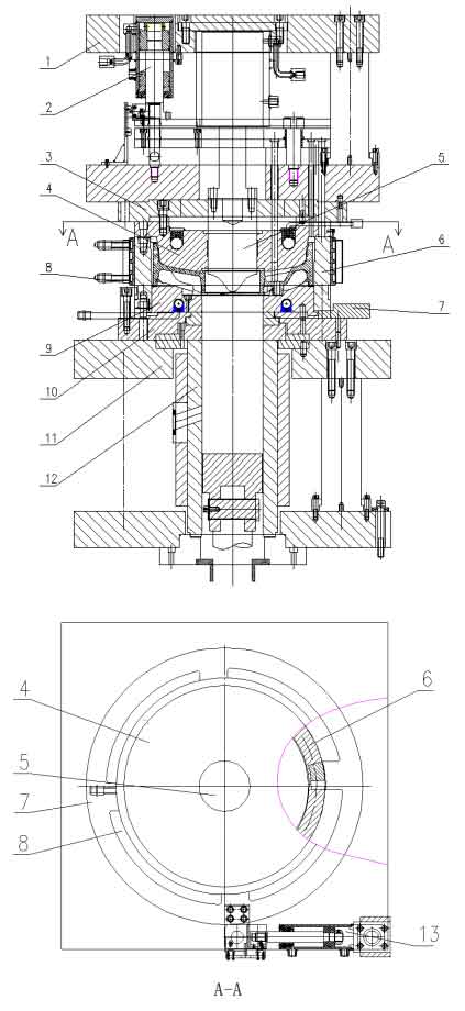
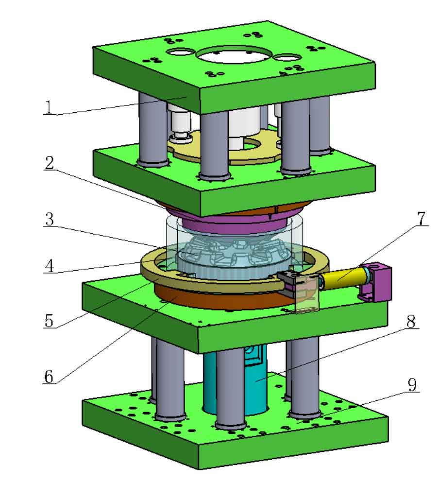
It can be seen that in the direct squeeze casting of large parts, the method of using elastic connection to support the moving ring has high requirements for the guiding accuracy of the moving ring, otherwise the yield of production will be difficult to guarantee. Aiming at the limitation of forming large parts with elastic support structure, a floating rigid support die structure is proposed. Figure 5 shows the floating rigid support mold used for forming large parts, which is mainly composed of upper mold base, upper mold, lower mold, lower mold base, moving ring, moving ring cushion block, side hydraulic cylinder and other parts. The upper mold base is fixedly connected with the movable beam of the vertical hydraulic press, and overflow grooves are set at the contact between the upper mold and the moving ring. The three-dimensional schematic diagram of the floating rigid support mold is shown in Figure 6.
The floating structure of the die is mainly composed of moving coil, moving coil cushion block and side hydraulic cylinder. Four helical surfaces a (as shown in Fig. 7 A) uniformly distributed at the bottom of the moving coil are matched with four helical surfaces B (as shown in Fig. 7 b) uniformly distributed at the moving coil cushion block, and the rise angle of the helical surface is α。 The pin fixed on the lower die base is matched with the pin hole of the moving ring to limit that the moving ring and the lower die only move axially. The moving coil cushion block is driven by the side hydraulic cylinder, and the stroke of the piston in the side hydraulic cylinder is limited by the stroke switch. By setting the contact position of the stroke switch of the side hydraulic cylinder, the downward extrusion compression during the upper die extrusion can be adjusted.
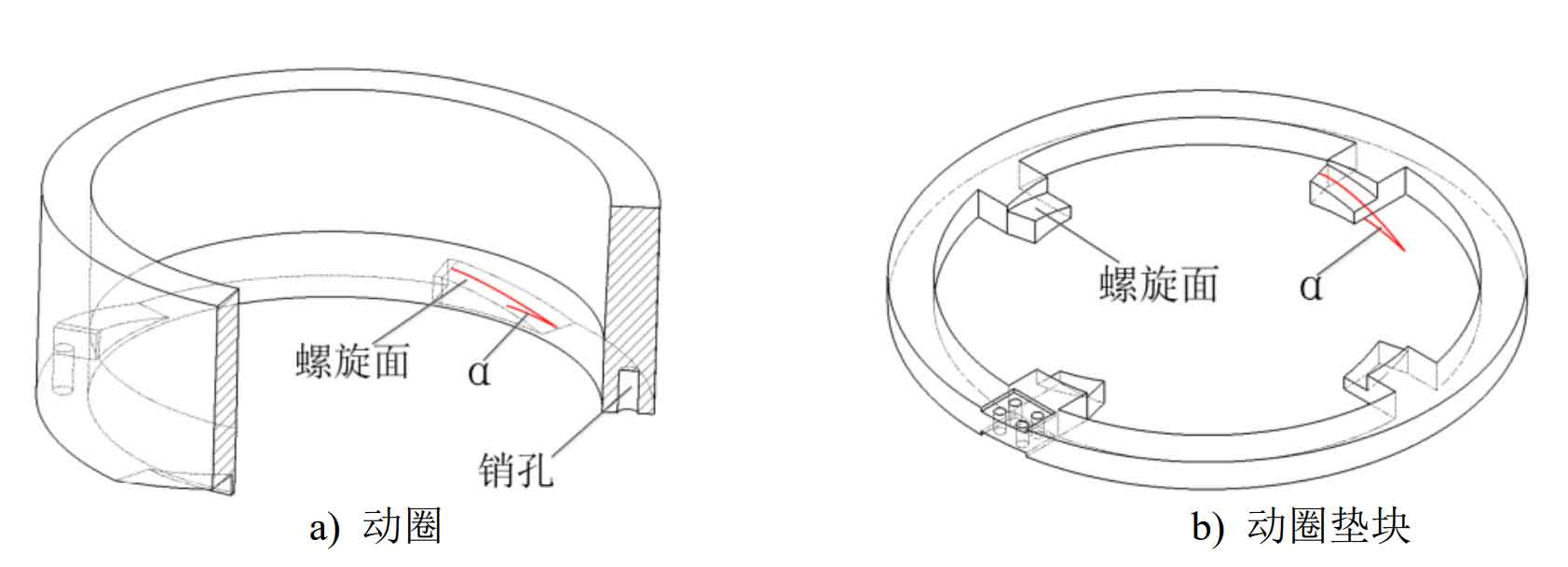
The rising angle of the spiral surface matched by the moving coil and the moving coil cushion block is 1~2 ° greater than the self-locking angle of the mechanism movement, so that when the mold filling is completed and the pressure of the side hydraulic cylinder is relieved, the moving coil will not descend rapidly due to the weight of itself and the upper die. When the upper die is pressed down, the moving coil can move under the pressure of the upper die, so there is no need for the side hydraulic cylinder and the main hydraulic cylinder driving the upper die to carry out complex oil circuit coordination. Therefore, the helix angle of the moving coil and the moving coil cushion block and the extrusion compression amount are two important parameters for the smooth operation of the mechanism.