
In the field of industrial valve manufacturing, the production of large, pressure-retaining components presents a significant set of challenges. As a foundry engineer with extensive experience in heavy-section castings, I have often been tasked with developing reliable processes for intricate shell castings. The specific case discussed here involves a large butterfly-type check valve body, a quintessential example of a complex shell casting requiring high integrity for critical service. This article details a first-person perspective on the methodology, calculations, and problem-solving approach employed to successfully cast these demanding shell castings, ensuring they meet stringent dimensional, aesthetic, and pressure-test requirements.
The valve body in question is a substantial component. Its external dimensions are approximately 674 mm in length and 350 mm in height, with a finished weight of 275 kg and a rough casting weight of 335 kg. The geometry is characterized by an arcuate central section flanked by two substantial flanges, creating a classic yet challenging shell-like structure. The wall thickness is highly variable, ranging from 22 mm in the thinner central regions to 65 mm at the flange junctions, with the largest identified thermal node (hot spot) having a diameter of Ø65 mm. The material specification is gray iron, HT200. Beyond the mechanical requirements of withstanding a 1.5 MPa test pressure without leakage, the casting must possess a sound, clean surface finish free from shrinkage cavities, slag inclusions, and cold shuts. Furthermore, raised logos and lettering must be sharp and aesthetically pleasing, adding to the difficulty as these are often located in challenging areas of the mold cavity.
The primary obstacles identified from prior experience with similar shell castings were dimensional distortion, specifically warping of the flanges, and difficulties in maintaining the precise parallel alignment and internal distance between the two flanges. These defects led to excessive machining allowances, assembly issues, and sometimes, scrapped castings. My objective was to design a process that inherently controlled these factors.
Determining the Foundry Process Plan
The first and most critical decision in any casting process is the selection of the parting line and mold orientation. For this valve shell casting, a vertical parting plane was chosen. This decision was driven by the need to manage distortion and ensure the stability of the sand cores defining the internal passages. Placing the majority of the mold cavity, including the lower flange and the complex central passage, in the drag (lower flask) provided inherent stability. A key innovation was the deliberate use of a large, specially-shaped sand core to replace the traditional chaplet or support system for the upper sections of the mold. This core not only formed critical internal features but also acted as a massive reinforcement for the entire mold structure, dramatically increasing its rigidity and resisting the mold wall movement that can lead to casting warpage. During core assembly, this design also allowed for a physical check of the internal distance between the flanges, providing an immediate quality control point.
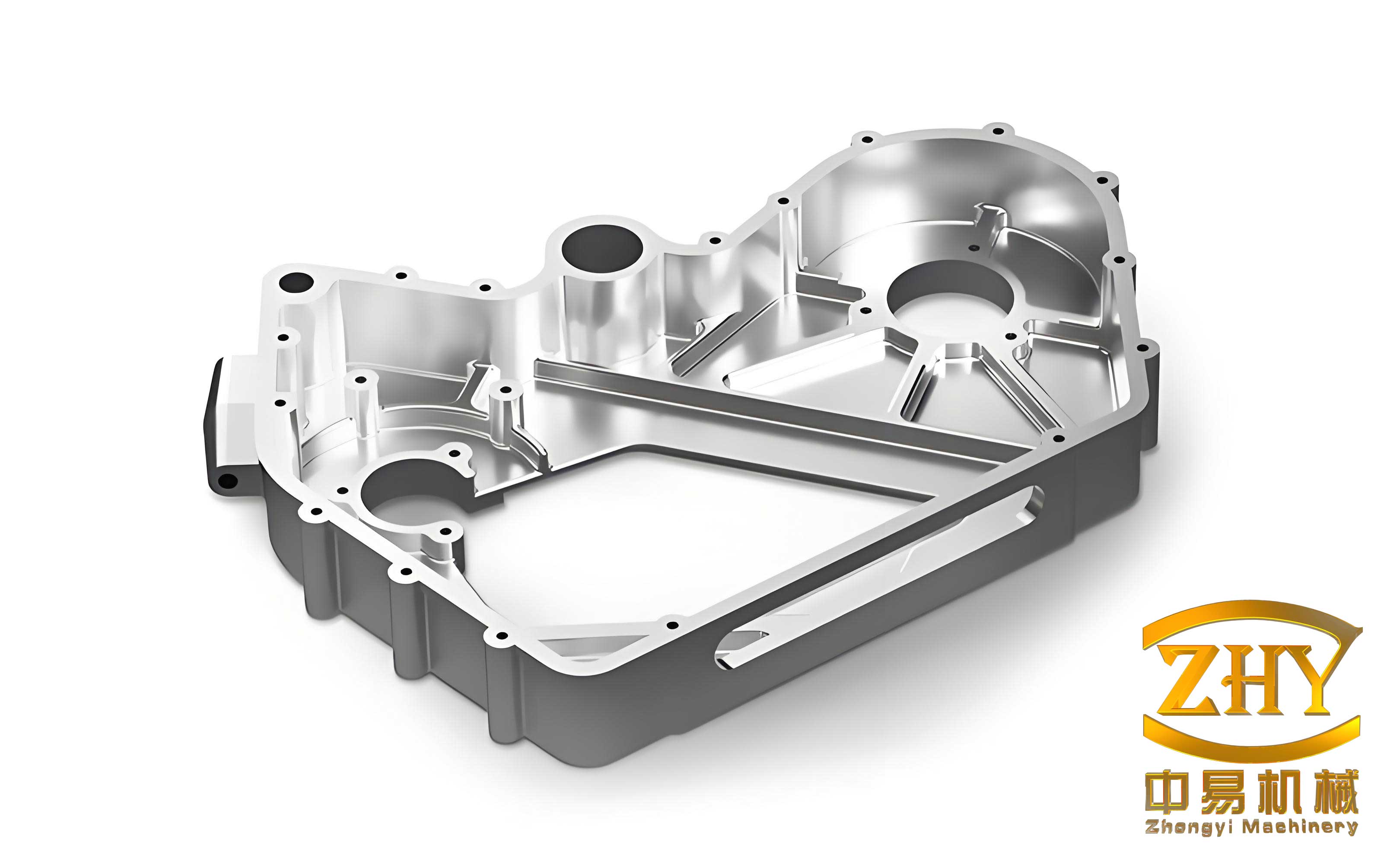
The upper flange was positioned in the cope (upper flask). This placement was strategic; locating a major machining surface on a core can lead to issues with core lift or shift during pouring, which directly impacts dimensional accuracy. By having it in the cope, its position is fixed relative to the mold exterior. The molding process utilized a surface-dried sand system for the main mold bodies, while the intricate logo and lettering sections were produced using more precise core sands to guarantee definition and avoid veining or erosion.
Accounting for shrinkage was nuanced due to the disparate section thicknesses. While a nominal linear shrinkage of 0.8% was applied globally, the interaction between the thin, rapidly solidifying center and the thick, slowly solidifying flanges created restrained contraction. To compensate for the resulting potential mismatch in flange spacing, a positive machining allowance, or “patternmaker’s shrink rule adjustment,” of 1.6 mm was added to the internal faces of each flange pattern. Furthermore, a “core print allowance” of 0.5 mm was applied to the mating surfaces of the core assemblies to ensure a proper fit after shrinkage. An additional 2 mm of thickness was added to the central cylindrical section’s nominal wall; this served as a safety margin against potential thin sections caused by core shift and was crucial for guaranteeing pressure tightness in the final shell castings.
Designing the Gating and Feeding System for Shell Castings
The design of the metal delivery and feeding system is paramount for the quality of heavy-section shell castings. The goal was to achieve a smooth, non-turbulent fill from the bottom upwards, promote favorable temperature gradients for directional solidification, and effectively compensate for volumetric shrinkage.
Gating System Design: The base of the lower flange was selected as the point of metal entry. This bottom-gating approach helps maintain a calm melt front and allows slag to float upwards, away from the critical pressure-containing walls of the shell castings. A semi-pressurized gating system was chosen for its good balance between slag trapping and flow control. The key parameters were determined through empirical calculations.
First, the pour time \( t \) (in seconds) was estimated based on the casting weight \( G \) (in kg):
$$ t = S \sqrt{G} $$
Where \( S \) is an empirical coefficient dependent on casting thickness. For a mean wall thickness around 30-40 mm, \( S \approx 1.63 \). With \( G = 335 \) kg:
$$ t = 1.63 \times \sqrt{335} \approx 30 \text{ seconds} $$
Next, the total cross-sectional area of the ingates \( \sum F_{ingate} \) (in cm²) was calculated using the fluidity factor method:
$$ \sum F_{ingate} = \frac{G}{0.31 \mu \sqrt{H_p}} $$
Where:
- \( \mu \) is the total flow resistance coefficient (taken as 0.48 for a semi-pressurized system with some turbulence).
- \( H_p \) is the effective metallostatic pressure head (in cm). For a bottom-gated casting of this height, the average head \( H_p \) was calculated to be approximately 42 cm.
Substituting the values:
$$ \sum F_{ingate} = \frac{335}{0.31 \times 0.48 \times \sqrt{42}} \approx 12.6 \text{ cm}^2 $$
This calculated value was cross-checked against established industry charts for gray iron, confirming its validity. Seven triangular ingates were employed to distribute the metal flow evenly around the lower flange circumference. The runner was placed on the large core, just above the lower flange, following its curved shape for approximately 2/5 of its perimeter. The final area ratios for the semi-pressurized system were set as:
$$ \sum F_{ingate} : \sum F_{runner} : F_{sprue\ bottom} = 1 : 1.5 : 1.2 $$
Thus:
$$ \sum F_{runner} = 1.5 \times 12.6 \approx 17.4 \text{ cm}^2 $$
$$ F_{sprue\ bottom} = 1.2 \times 12.6 \approx 15.1 \text{ cm}^2 $$
This corresponds to a sprue bottom diameter of approximately 44 mm.
Feeding System (Risering) Design: The thick flange sections are clear candidates for feeding. The traditional “hot spot” or “inscribed circle” method was used to size the risers. For a thermal node diameter \( d_y = 65 \) mm, the riser dimensions were calculated as follows:
1. Riser Neck Diameter (\(d\)): Must be large enough to remain liquid longer than the hot spot but not create a new, larger hot spot.
$$ d = 0.85 \times d_y = 0.85 \times 65 \approx 55 \text{ mm} $$
2. Riser Diameter (\(D\)): Must provide sufficient feed metal volume.
$$ D = 1.4 \times d_y = 1.4 \times 65 = 91 \text{ mm} $$
3. Riser Height (\(H\)): Typically 1.5-2.0 times the diameter to promote thermal gradient.
$$ H = 2.0 \times D = 2.0 \times 91 \approx 180 \text{ mm} $$
Three top risers were placed directly on the upper flange sections. To verify the adequacy of the feeding, a feed volume check was performed. The estimated solidification shrinkage for gray iron is about 0.8-1.0%. Taking a conservative 1.0%, the feed metal required is:
$$ 335 \text{ kg} \times 1.0\% = 3.35 \text{ kg} $$
The volume of one cylindrical riser is:
$$ V_{riser} = \pi \times (D/2)^2 \times H = \pi \times (4.55)^2 \times 18 \approx 1170 \text{ cm}^3 $$
With a density of ~7.1 g/cm³, the riser weight is ~8.3 kg. Assuming a feeding efficiency (yield) of 14% (typical for gray iron risers without exothermic aids), the available feed metal per riser is:
$$ 8.3 \text{ kg} \times 14\% \approx 1.16 \text{ kg} $$
For three risers, total available feed is ~3.48 kg, which exceeds the required 3.35 kg, confirming the design as adequate for these shell castings.
The following table summarizes the key process parameters for these valve shell castings:
| Parameter Category | Specification / Value |
|---|---|
| Casting Material | Gray Iron HT200 |
| Casting Weight (Rough) | 335 kg |
| Nominal Linear Shrinkage | 0.8% |
| Flange Spacing Allowance | +1.6 mm per side |
| Core Print Allowance | 0.5 mm |
| Central Wall Safety Allowance | +2.0 mm |
| Gating System Type | Semi-pressurized, Bottom-gated |
| Number of Ingates | 7 (Triangular section) |
| Total Ingate Area | ~12.6 cm² |
| Pour Time | ~30 seconds |
| Number of Risers | 3 (Top cylindrical) |
| Riser Diameter/Height | Ø91 mm / 180 mm |
| Mold/Core Media | Surface-dried Sand / Precision Core Sand for details |
Solidification Analysis and Defect Prevention Strategy
For complex shell castings, a theoretical understanding of the solidification sequence is essential. The thin-walled central section will solidify first, creating a rigid bridge between the two flanges. The flanges, with their much higher modulus (Volume/Surface Area ratio), will solidify later. This creates a condition where the shrinkage of the flanges is restrained by the already-solid center, putting the flange junctions into tension and increasing the risk of micro-porosity or even hot tearing in more sensitive alloys. The risers are therefore critically placed to feed these flange junctions *last*, ensuring they remain liquid long enough to receive feed metal and solidify soundly.
The temperature gradient \(G\) and solidification rate \(R\) are key parameters. While detailed simulation provides exact values, we can approximate the intention. The chill effect of the mold and the strategic placement of risers aim to achieve a gradient where \(G/R\) is sufficiently high in the flange-riser junction to promote directional solidification towards the riser, a condition described by the thermal gradient equation relevant to feeding:
$$ \nabla T = \frac{\partial T}{\partial x} $$
Where a steeper positive gradient towards the riser is desirable. The use of chills was considered but deemed unnecessary due to the effectiveness of the designed riser necks and the controlled heat extraction from the large core acting as an internal chill on the thin walls of the shell castings.
Potential defects and their countermeasures were systematically addressed:
| Potential Defect | Root Cause in Shell Castings | Applied Countermeasure in this Process |
|---|---|---|
| Flange Warpage | Uneven cooling stresses, mold wall movement. | Use of reinforcing sand core in drag; symmetrical gating and risering. |
| Dimensional Inaccuracy (Spacing) | Pattern shrinkage inaccuracy, core shift. | Application of positive allowances on pattern and core prints; physical check during core assembly. |
| Shrinkage Porosity at Hot Spots | Inadequate feed metal or poor feeding path. | Risers sized via hot-spot method, placed directly on flange junctions with calculated necks. |
| Slag Inclusions | Turbulent filling, poor slag trapping. | Bottom gating with semi-pressurized system; large runner for slag buoyancy. |
| Poor Surface Finish (Logos) | Erosion of fine sand details. | Use of high-strength, precision core sand for logo/lettering inserts. |
Process Validation and Results
The implementation of this engineered process yielded highly positive results for the production of these shell castings. The dimensional consistency was markedly improved. Flange thickness variation was controlled within +1 to +2 mm of nominal, and the critical internal distance between flanges was held within a tolerance of -2 to -3 mm, achieving a dimensional accuracy level equivalent to IT12 grade. This level of precision minimized machining stock and ensured proper fit during valve assembly.
More importantly, the internal soundness of the castings was validated. All pressure tests were passed successfully with no instances of leakage or weeping, confirming the absence of interconnected shrinkage or gas porosity within the pressure boundary walls of the shell castings. The surface finish was clean and smooth, meeting the specified aesthetic requirements, with the raised logos and markings being sharply defined.
This case underscores that successful production of heavy-section, complex shell castings relies not on a single silver bullet, but on a holistic and analytically supported process design. Key takeaways include:
- Strategic Mold Design: Using sand cores for both form and structural reinforcement can effectively combat distortion in large shell castings.
- Calculated Allowances: Applying allowances for shrinkage, core shift, and safety margins is a non-negotiable step for dimensional precision.
- Systematic Gating/Risering: Even for well-known materials like gray iron, empirical calculations for pour time, gate sizes, and riser dimensions are indispensable for achieving soundness and yield.
- Defect-Driven Planning: Anticipating potential defects based on geometry and material behavior allows for pre-emptive countermeasures to be built directly into the process.
The methodology described here, blending empirical foundry science with practical design innovations, provides a robust framework for tackling the challenges associated with large, pressure-containing shell castings across various industries. The principles of controlled filling, directional solidification, and proactive distortion management are universally applicable, ensuring the reliable manufacture of high-integrity components.
Advanced Considerations for Future Shell Castings
Looking forward, the process for such shell castings can be further refined and optimized. Modern tools like solidification simulation software allow for virtual testing of different riser configurations, chill placements, and gating designs before any metal is poured. This can lead to optimized yields and reduced development time. Furthermore, the chemical composition of the iron can be fine-tuned. For instance, a slight adjustment in the carbon equivalent (CE) can influence the graphitization expansion, which can be used to counter the shrinkage porosity, potentially allowing for smaller risers. The carbon equivalent is calculated as:
$$ CE = \%C + \frac{1}{3}(\%Si + \%P) $$
Controlling CE within an optimal range (typically 3.9-4.2 for HT200) is crucial for achieving the right balance of strength, castability, and shrinkage behavior in these shell castings. Additionally, the use of inoculants to control graphite morphology directly impacts tensile strength and thermal conductivity, further influencing the solidification characteristics and final properties of the shell castings. The table below outlines some key alloying and process elements for advanced control:
| Control Element | Target Influence | Consideration for Shell Castings |
|---|---|---|
| Carbon Equivalent (CE) | Fluidity, Shrinkage/Expansion Balance, Strength | Higher CE improves fluidity for thin walls but may reduce strength. Must be optimized for the specific section modulus. |
| Inoculation (e.g., FeSi) | Graphite Nucleation, Structure Uniformity | Essential for ensuring uniform mechanical properties across varying section thicknesses in a single shell casting. |
| Mold Rigidity | Resistance to Mold Wall Movement | High rigidity is non-negotiable for dimensional accuracy; achieved through sand compaction, reinforcement, and flask strength. |
| Pouring Temperature | Fluidity, Microstructure, Shrinkage | Must be high enough to fill thin sections and logos but low enough to minimize total heat content and shrinkage volume. An optimal range is critical. |
In conclusion, the journey from a challenging casting drawing to a successfully pressure-tested component is a testament to systematic engineering. By dissecting the geometry of the shell castings, applying fundamental principles of fluid flow and heat transfer, and implementing clever mold design solutions, what was once a problematic production item can be transformed into a reliable, high-quality casting. The satisfaction of seeing such components perform flawlessly in service is the ultimate validation of the foundry engineer’s craft.