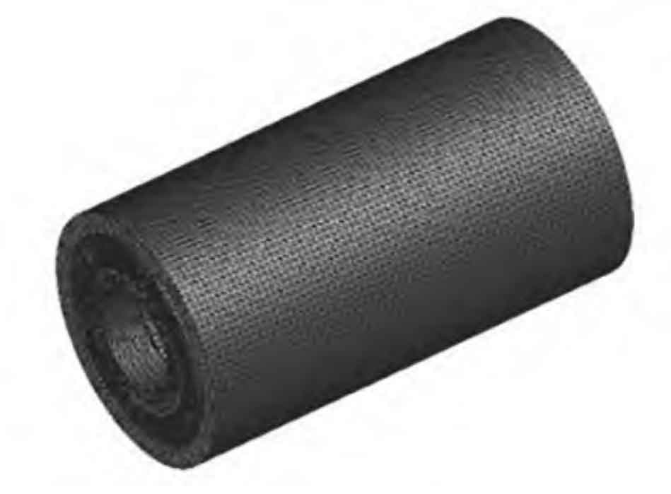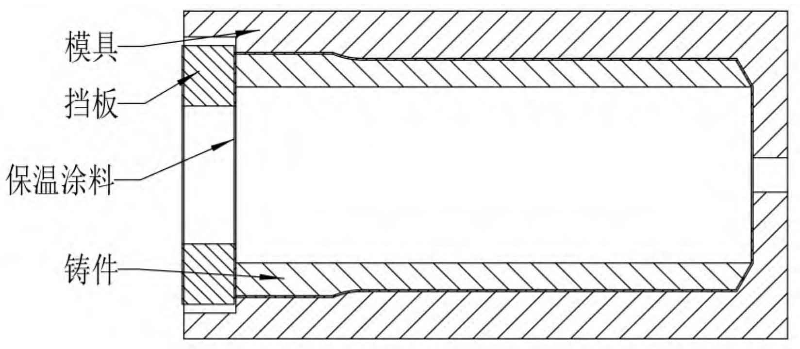
The assembly diagram of centrifugal casting parts and molds is shown in Figure 1. The maximum diameter of centrifugal casting parts is 40mm, the length is 298mm, and the maximum wall thickness is 19mm. The distribution diagram of the blank and machining allowance of the centrifugal casting is shown in Figure 2. The machining allowance of the single side of the inner hole is 7-9mm, the machining allowance of the pouring end is 40mm, and the machining allowance of the tail end is 20mm.
The unstructured tetrahedral grid is used to grid the mold, baffle, centrifugal casting parts and thermal insulation coating, increase the grid density of thermal insulation coating and centrifugal casting parts, and increase the grid size of mold and baffle to reduce the amount of calculation. The pouring position is set on the internal surface of centrifugal casting parts, with the number of surface grids of 99812 and the number of volume grids of 719843. The grid division results are shown in Figure 3.