1. Determination of welding and Pouring Scheme
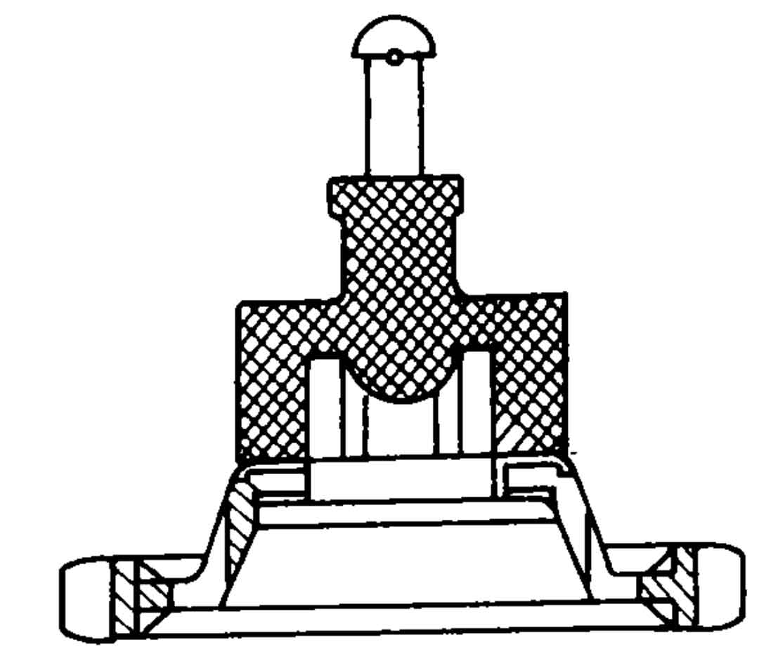
Whether the selection of welding and pouring scheme is reasonable or not is not only related to whether the internal quality and appearance quality of precision castings can be guaranteed, but also directly affects the processes such as shell making, dewaxing, roasting and handling. Through the comparison and test of various schemes, it is decided to adopt the top injection scheme with the tooth shape downward, as shown in Figure 1. The scheme has the following three advantages:
a. The tooth profile of precision casting is downward, and the pouring dynamic pressure and static pressure are the maximum, so that the tooth profile profile remains clear, and the dimensional accuracy and internal quality are guaranteed;
b. The welding between the pouring system and the wax mold of precision casting is easy and simple;
c. Due to the large volume and heavy weight of precision castings, the shell making operation, dewaxing and handling can be carried out with the help of small lifting machinery to reduce the labor intensity of workers.
2.Determination of line collection rate
Since the 23 teeth of the driving wheel and most of its related geometric dimensions are directly precision cast and shaped, whether the linear shrinkage is selected accurately in the design of the die is very important for whether the precision casting can meet the drawing requirements after forming and ensure the normal operation of the whole machine. It is well known that the linear shrinkage rate used in the design of wax mold is the comprehensive shrinkage rate considering three factors: wax mold shrinkage, shell baking expansion and metal shrinkage. The linear shrinkage rate of different shell making processes and mold materials is different. ZHY casting uses paraffin stearic acid molding material, water glass binder, chlorinated press hardener, quartz powder in surface coating and bauxite powder in reinforcement coating. Combined with the actual production conditions and many years of experience of our factory, after many careful tests, the linear shrinkage is selected between 1.8% and 2.2%. The use principle of linear shrinkage rate is: the upper limit for large size, the middle limit for large size, the lower limit for small size, and no shrinkage for small size.
3. Design principles and dimensions of pouring system
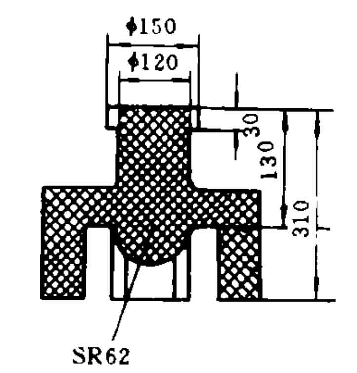
3.1 the design of pouring system is an important part of precision casting process design, which is directly related to the internal quality and process yield of precision castings. When the driving wheel adopts the top injection scheme, because the tooth shape of the precision casting is at the same level as most of the wheel width and occupies a large surface area, the alloy liquid level rises slowly at the conventional pouring speed, which is easy to produce wrinkles and sand inclusion. In order to ensure the clear outline of the teeth, large flow and rapid pouring must be adopted at the initial stage of pouring (before pouring the full tooth height). Therefore, the pouring system adopts an open pouring system.
3.2 the wax mold of the precision casting of the driving wheel is heavy (about 20 kg). In order to make the welding between it and the pouring system firm and reliable, the inner gate is not set between the riser and the precision casting, but the wax mold of the precision casting is directly welded at the bottom of the riser. The safe height of the riser is improved by appropriately increasing the height of the riser to prevent shrinkage porosity or shrinkage cavity of the precision casting.
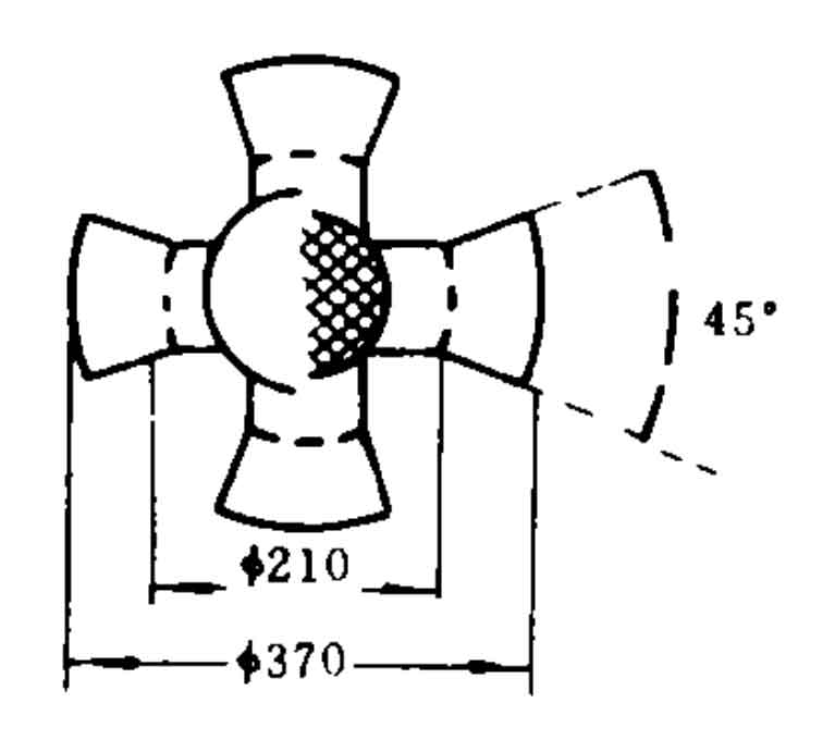
3.3 a hemispherical slag collecting bag with a diameter greater than the diameter of the sprue shall be set directly below the sprue to make the falling sand of the mold shell gather in the bag during dewaxing, roasting and handling. Before pouring, it shall be sucked out with a straw to prevent the sand from falling into the teeth of the precision casting and causing sand inclusion defects. The structure and dimensions of the pouring system are shown in Figure 2


