
In the field of metal casting, the prediction and control of casting defects are critical for ensuring product quality and reducing manufacturing costs. As a researcher focused on alloy casting process optimization, I have conducted a comprehensive study on the casting of ductile iron crankshafts, leveraging advanced simulation software to predict casting defects and validating these predictions through experimental trials. This article details the entire process, from material property calculation to simulation analysis and physical verification, emphasizing the importance of numerical simulation in mitigating casting defects.
The advent of computer technology and software development has laid a solid foundation for the digitization of the casting industry. The application of casting simulation software enables the optimization of casting processes, allowing for the analysis of common casting defects such as shrinkage porosity, cracks, and oxide inclusions. By simulating and refining process parameters, it is possible to significantly reduce casting defects, shorten development cycles, and lower costs associated with process exploration. In this study, I utilized EKK CAPCAST casting simulation software to model the casting process of a ductile iron crankshaft, predicting the types, locations, and sizes of potential casting defects during mold filling and solidification. These predictions were then compared with actual production trials to verify their accuracy.
To ensure the simulation reflects real-world conditions, accurate thermophysical properties of the material are essential. The ductile iron grade used, QT820-3, has a specific chemical composition, as summarized in Table 1. Since EKK CAPCAST does not contain built-in data for this alloy, I employed JMatPro software to calculate key parameters such as density, thermal conductivity, specific heat, and phase transition temperatures. The solidus temperature was determined to be 1140°C, the liquidus temperature 1164°C, and the latent heat of fusion 258 J/g. These properties are crucial for accurately simulating heat transfer during casting, which directly influences the formation of casting defects.
| Element | Content (wt%) |
|---|---|
| C | 3.7 |
| S | 0.01 |
| Si | 2.45 |
| Mn | 0.32 |
| P | 0.05 |
| Cr | <0.1 |
| Sn | 0.02 |
| Ti | 0.02 |
| Cu | 1.15 |
| Mg | 0.04 |
| Fe | Balance |
The three-dimensional model of the crankshaft, including the gating system, risers, and chills, was created in UG software and exported as an STL file. This model was imported into the EKK CAPCAST pre-processing module, MESHID, for meshing and setup. Given the complex geometry of the crankshaft, a fine mesh of approximately 3 million elements was generated to ensure computational accuracy. The casting type was specified as sand casting with green sand molds. Initial conditions included a pouring temperature of 1390°C and a pouring speed of 1.1 m/s. These parameters were chosen based on typical production practices to simulate real-world conditions closely.
The mold filling process was simulated to assess flow behavior and potential turbulence. The results indicated that the molten iron filled the mold cavity smoothly from the bottom upward, driven primarily by gravity. The gating system was designed with a decreasing cross-sectional area from the sprue to the runner and then to the ingates, promoting accelerated flow into the cavity. This design minimized turbulent flow, thereby reducing the risk of gas entrapment, sand erosion, and other filling-related casting defects. The entire filling process was stable, with no significant splashing or vortex formation observed, which is beneficial for defect prevention.
Following filling, the solidification process was analyzed to identify regions prone to casting defects. The simulation revealed that areas with smaller modulus, such as thin sections, solidified first, while regions with larger modulus, like the main journal necks, solidified later. Of particular interest was the fourth main journal neck, where a large isolated molten pool formed due to premature solidification of the adjacent third crankpin neck, accelerated by chills. This isolation prevented adequate feeding from the riser, leading to significant shrinkage stresses during solidification. The volume of this isolated pool and the predicted defect formation region were quantified, as shown in Table 2. The predicted shrinkage crack defect volume was approximately 6 mm³, highlighting a critical area for casting defects.
| Crankshaft Identifier | Isolated Molten Pool Volume (mm³) | Predicted Defect Formation Volume (mm³) |
|---|---|---|
| A | 44.10 | 6.36 |
| B | 43.20 | 6.04 |
| C | 44.10 | 6.17 |
| D | 43.84 | 6.00 |
The formation of casting defects in ductile iron is often governed by thermal gradients and solidification kinetics. The solidification time for a region can be estimated using the Chvorinov’s rule, expressed as: $$ t_s = C \left( \frac{V}{A} \right)^n $$ where \( t_s \) is the solidification time, \( V \) is the volume, \( A \) is the surface area, \( C \) is a constant dependent on mold material and pouring conditions, and \( n \) is an exponent typically around 2. For the isolated molten pool in the fourth main journal, the high \( V/A \) ratio (modulus) leads to prolonged solidification, increasing the risk of shrinkage-related casting defects. Additionally, the stress developed due to thermal contraction can be modeled using: $$ \sigma = E \alpha \Delta T $$ where \( \sigma \) is the thermal stress, \( E \) is Young’s modulus, \( \alpha \) is the coefficient of thermal expansion, and \( \Delta T \) is the temperature difference. In regions with late solidification, such as the isolated pool, the accumulated stress may exceed the material’s strength, resulting in cracks—a severe type of casting defect.
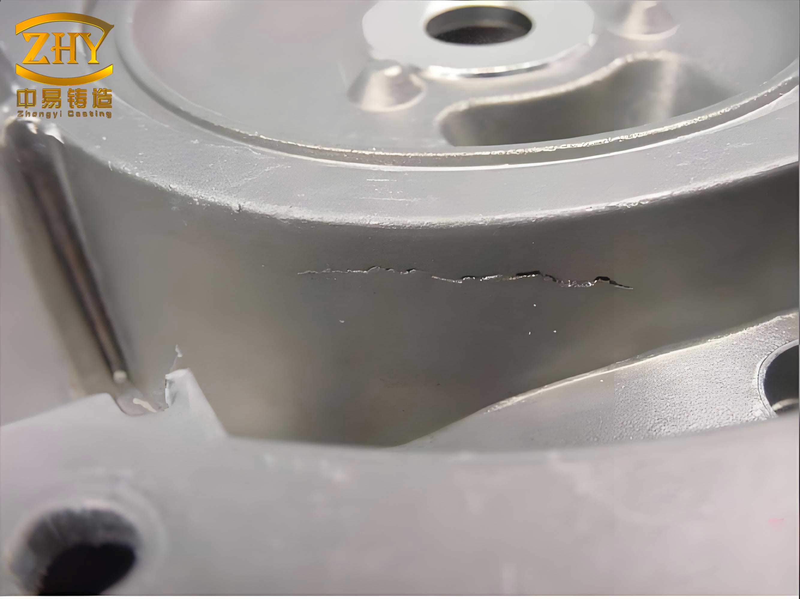
To validate the simulation predictions, production trials were conducted using the same process parameters. After casting, the crankshafts were sectioned at the predicted defect location in the fourth main journal. Macroscopic examination revealed a crack defect approximately 10 µm in width, enveloping a spherical region akin to the predicted volume. This confirms the accuracy of the simulation in identifying casting defects. Microstructural analysis was performed on samples extracted from the defect area and its surroundings. The specimens were mounted, polished, and etched with 4% nital solution for metallographic observation using an optical microscope. Hardness measurements were taken using a Vickers microhardness tester.
The results showed distinct differences between the interior and exterior of the crack. The graphite nodules within the crack-enclosed region were smaller in size compared to those outside, indicating asynchronous solidification. The average hardness inside the crack was about 30 HV lower than outside, suggesting elemental segregation and reduced carbide formation due to late solidification. These findings align with the simulation prediction that the isolated molten pool solidified later, leading to microstructural inhomogeneities and the formation of casting defects. The image below illustrates typical casting defects observed in such scenarios, underscoring the importance of simulation in defect prediction.
Further analysis of the casting defects involves considering the role of alloy composition and cooling rates. Ductile iron has a wide solidification range, which promotes mushy zone formation and increases susceptibility to shrinkage porosity and cracks. The carbon equivalent (CE) can be calculated as: $$ \text{CE} = \%\text{C} + \frac{1}{3}(\%\text{Si} + \%\text{P}) $$ For QT820-3, the CE is approximately 4.5%, indicating a high graphite precipitation potential. During solidification, graphite expansion can compensate for shrinkage, but in isolated regions, this compensation is inadequate, leading to casting defects. The simulation software accounts for these phenomena by solving the heat transfer and fluid flow equations numerically. The general heat conduction equation is: $$ \rho c_p \frac{\partial T}{\partial t} = \nabla \cdot (k \nabla T) + Q $$ where \( \rho \) is density, \( c_p \) is specific heat, \( k \) is thermal conductivity, \( T \) is temperature, \( t \) is time, and \( Q \) represents heat sources such as latent heat. By integrating material properties from JMatPro, the simulation accurately captures thermal gradients that drive defect formation.
Based on the simulation and experimental results, process optimizations were proposed to mitigate casting defects. For instance, adding chills at the first crankpin neck could accelerate cooling of the first and second main journals, reducing their solidification time and minimizing defect risks. Additionally, enlarging the neck of the end riser would improve feeding to the fourth main journal, eliminating the isolated molten pool and associated casting defects. These modifications demonstrate how simulation-driven design can enhance casting quality. To summarize the key parameters influencing casting defects in this study, Table 3 provides an overview of the simulation inputs and outputs.
| Aspect | Details | Impact on Casting Defects |
|---|---|---|
| Material | Ductile Iron QT820-3 | Wide solidification range increases defect susceptibility |
| Pouring Temperature | 1390°C | Higher temperatures may reduce viscosity but increase shrinkage |
| Gating Design | Decreasing cross-sectional area | Promotes smooth filling, reduces turbulence-related defects |
| Cooling Conditions | Chills at crankpins | Accelerates solidification, but may isolate regions causing defects |
| Predicted Defect Volume | ~6 mm³ in fourth main journal | Directly identifies location and size of casting defects |
| Experimental Validation | Crack observed in fourth main journal | Confirms simulation accuracy for casting defects prediction |
In conclusion, this study successfully demonstrates the use of EKK CAPCAST software to predict casting defects in ductile iron crankshafts. The simulation accurately forecasted the formation of a shrinkage crack defect in the fourth main journal due to an isolated molten pool, with a predicted volume of about 6 mm³. Production trials confirmed this prediction, revealing a crack defect of comparable size. Microstructural and hardness analyses further validated the asynchronous solidification responsible for the casting defects. The findings underscore the value of numerical simulation in optimizing casting processes to prevent casting defects. Future work could explore additional alloy grades or complex geometries to broaden the applicability of this approach. Ultimately, integrating simulation with experimental verification provides a robust framework for enhancing casting quality and efficiency, minimizing the occurrence of costly casting defects in industrial production.
The prevention of casting defects remains a central challenge in foundry operations. By leveraging advanced tools like EKK CAPCAST and JMatPro, engineers can proactively identify and address potential issues, reducing scrap rates and improving product reliability. The key takeaways from this research include the importance of accurate material data, the role of gating and cooling design in defect formation, and the necessity of experimental validation. As casting simulation technology continues to evolve, its integration into standard practice will further mitigate casting defects, driving innovation in the manufacturing sector. This holistic approach—combining simulation, experimentation, and optimization—is essential for tackling the multifaceted nature of casting defects in modern metalcasting.