
Screen plates are the working elements of roller-type coal crushers used in the coarse-crushing stage of thermal power plants. Large lumps of coal are struck and sheared between high-speed rotating toothed screens and the crushing drum before being conveyed to the fine-crushing stage. The plates therefore operate under combined compressive and shear loading and are classified as wear parts. Their geometry combines a central mounting bore with a ring of crushing teeth, and the bore must remain clean and machinable because it locates the plate on the shaft.
Because the duty is abrasive rather than structural, the economic case for a casting route rests on dimensional consistency, surface integrity and, above all, freedom from near-surface and internal defects. Conventional production used water-glass-bonded CO2-hardened sand molds, a process that repeatedly produced sand holes, gas porosity and slag inclusion in these plates. Defects that open up after grinding and rough machining either interrupt the machining sequence or scrap the casting outright. Replacing the sand process with lost foam (evaporative pattern) casting addresses the problem at its origin: a rigid foam pattern is consumed by the incoming metal, so the mold cavity is formed by the pattern rather than by a withdrawn or broken-down core, and the dry unbonded sand backing can be compacted uniformly around the whole plate.
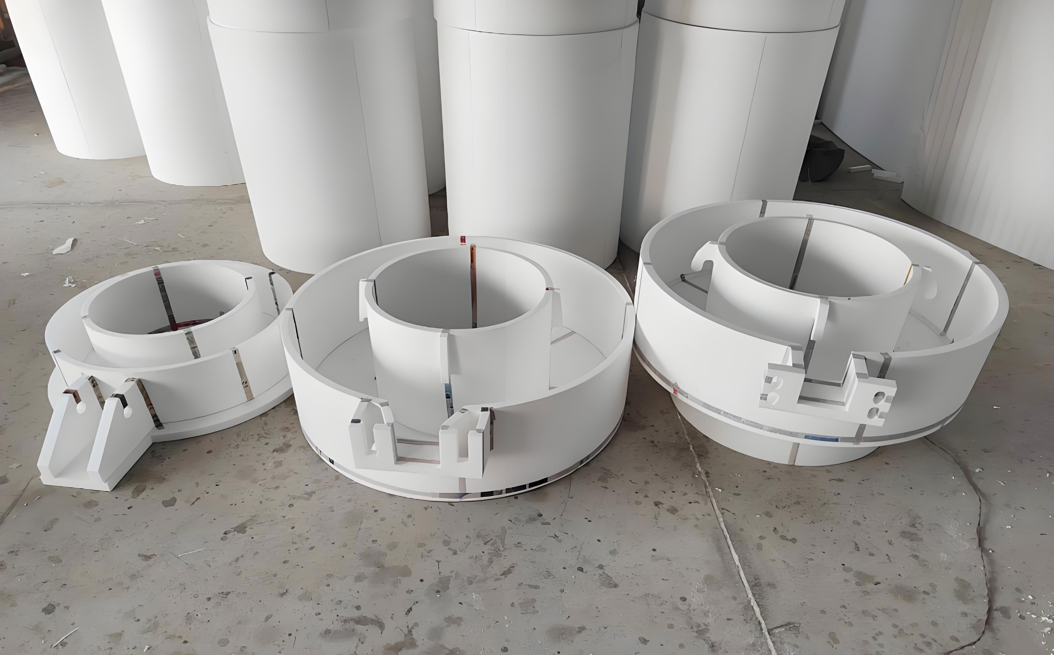
What the change of process delivers
Production data collected on the two routes give a direct comparison. In the sand process a flask carries four plates, and of every 20 plates cast roughly four are scrapped because porosity and sand holes interfere with subsequent machining, giving a yield of about 80%. In the lost foam process a flask carries six plates, so the output per molding cycle is 1.5 times higher, and the casting yield reaches 100%, i.e. 1.25 times that of sand casting. The lost foam plates show no surface defects after grinding and cleaning, and ultrasonic inspection finds no significant internal discontinuities, with the inspected plates meeting quality grade 3.
Part of the gain comes from gating and feeding rather than from the process itself. A first trial using a vertical orientation of the plates produced severe burn-on inside the central bore, which could not be machined and scrapped the castings. The cause was insufficient compaction of the dry sand in the bore cavity of a vertically stacked cluster, allowing liquid metal to penetrate the sand. Reorienting the plates horizontally and placing a feed riser above each bore eliminated the burn-on completely, and porosity, sand holes and slag inclusion dropped accordingly. The defect counts per single casting, averaged over production batches, are summarized below.
| Process | Gas porosity (per piece) | Sand holes (per piece) | Slag inclusion (per piece) | Burn-on |
|---|---|---|---|---|
| Water-glass CO2 sand casting | 3.2 | 2.8 | 3.1 | None |
| Lost foam, vertical pouring | 1.3 | 1.2 | 1.0 | Present (bore) |
| Lost foam, horizontal pouring with riser | 0.3 | 0.2 | 0.1 | None |
Pattern making in polystyrene
Patterns are cut by hand from expanded polystyrene using a resistance wire. Pattern density is the single most consequential variable in the whole process. A foam that is too light lacks the stiffness to support the coating and the sand bed, so the pattern distorts during compaction or the mold collapses; a foam that is too dense generates excessive pyrolysis products, so carbon pickup, internal porosity and inclusions increase and the metal front fills the cavity sluggishly. Trials across a range of densities settled on 0.016–0.018 g/cm3 as the best compromise.
Pattern surfaces must be smooth, free of pronounced ridges and hollows, with well-fused beads and no foreign matter trapped inside the section. A linear shrinkage allowance of 1.02% relative to the finished part is applied to the pattern dimensions. Sections are joined with polyvinyl acetate (white) adhesive, and the assembled pattern is dried for 24–48 h. Drying serves two purposes: it prevents distortion of the glued assembly before molding, and it removes moisture that would otherwise flash to steam during pouring and cause back-pressure, metal spitting or gas porosity.
Refractory coating
The coating controls surface quality and also stiffens the pattern for handling. The refractory filler is quartz powder with a density of 2.65 g/cm3 and a thermal conductivity of 1.8 W/(m·K); water is the carrier, cellulose the suspending agent and polyvinyl acetate the binder. The slurry is homogenized in a ball mill for 4–6 h before use, and the coated pattern is dried in an infrared oven at 52 ± 3 °C. A sound coating limits burn-on and sand holes and preserves pattern rigidity during transport and during sand raining and vibration.
Gating, feeding and sand compaction
In the horizontal layout, ingates of 45 mm × 45 mm are attached to the crushing teeth and a 50 mm × 50 mm runner is arranged symmetrically on both sides of the sprue, forming an open (non-pressurized) gating system that feeds six plates per flask. Sand boxes are of the bottom-suction vacuum type.
Compaction follows a fixed sequence. A bed of dry sand 100–200 mm deep is placed in the flask and vibrated, after which the sand surface is leveled. The pattern cluster is checked for exposed “white” areas where the coating has been rubbed through, and any such area is sealed at once with refractory mud. Sand is then added to half the pattern height and hand-filled beneath the plates. A second vibration stage runs while filling continues; after it ends, the sand beneath the plates is rammed with a wooden rod to rule out voids that would otherwise produce burn-on or dimensional drift.
Melting, pouring and vacuum
Melt is prepared in a 250 kg medium-frequency induction furnace from a charge calculated to the specified plate composition. The charge is packed densely, power is applied at a low level for the first 10 min and then raised to maximum once the current is stable, and the charge is pushed down periodically to prevent bridging. Composition is adjusted and deoxidation intensified after full melt-down.
Steel is tapped at 1 590–1 610 °C and held in the ladle for 3–5 min; pouring begins as soon as a film forms on the surface. Pouring rate has to match the rate at which the foam decomposes and its products escape. Too slow a pour lets the metal front lag behind pattern disappearance, enlarging the gas gap at the front and risking mold collapse; too fast a pour overwhelms the venting capacity of the coating and sand and causes back-pressure and spitting. Turbulent flow in the cavity promotes gas and slag entrapment. The practical rule is to fill the sprue and pouring cup quickly, hold a steady rate, then ease off as the mold fills, keeping a head of liquid metal in the cup.
Vacuum is maintained throughout pouring. The negative pressure is held at −0.06 to −0.04 MPa during filling and adjusted to −0.04 to −0.03 MPa afterwards, with the pump switched off after 15–20 min. Castings are held in the flask for 6 h before shakeout and then air-cooled.
| Parameter | Value |
|---|---|
| Pattern material / density | Expanded polystyrene, 0.016–0.018 g/cm3 |
| Pattern shrinkage allowance | 1.02% |
| Pattern drying | 24–48 h after gluing |
| Coating filler | Quartz powder, 2.65 g/cm3, 1.8 W/(m·K) |
| Coating mixing / drying | Ball mill 4–6 h; infrared oven 52 ± 3 °C |
| Gating system | Open; ingate 45 mm × 45 mm, runner 50 mm × 50 mm; 6 plates per flask |
| Tapping temperature | 1 590–1 610 °C |
| Vacuum during / after pouring | −0.06 to −0.04 MPa / −0.04 to −0.03 MPa for 15–20 min |
| In-flask holding | 6 h |
Heat treatment and hardness
Plates are quenched and tempered following standard heat-treatment practice for the grade, so that service hardness matches the duty. Brinell testing with a KPE300 instrument gives a surface hardness of HBS 243–269 after treatment, within the range specified for the application. The combination of a defect-free casting and a controlled quench-and-temper cycle is what allows the plate to be machined to final dimensions without exposing subsurface discontinuities.
Process implications
Three findings carry over to similar wear castings with a critical bore or other deep internal feature. First, orientation dominates sand compaction: a vertical stack of plates leaves the bore cavity poorly compacted and invites metal penetration, whereas a horizontal layout with the bore facing a compactable direction removes the problem. Second, a riser placed directly above the bore restores feeding to the last region to solidify and suppresses porosity and slag entrapment there. Third, the process economics come from flask loading and yield together — six plates per flask against four, and 100% against 80% — rather than from cycle time alone, since pattern cutting, coating and drying add steps that sand molding does not require.
The limitations follow the same logic. Hand cutting of foam patterns by resistance wire is adequate for a plate of this size but is difficult to hold to tight tolerances, and the 1.02% shrinkage allowance absorbs only part of the variation. Pattern density, coating thickness and drying schedule all need to be controlled batch by batch, because deviations show up as carbon pickup, porosity or distortion rather than as an obvious external fault. Within those constraints, lost foam casting provides a short, low-cost route to a fully sound crusher screen plate with higher output per molding cycle than water-glass CO2 sand casting.