
This paper systematically explores the application of lost foam casting (LFC) technology in manufacturing large-scale thin-walled transmission cases for tractors. Through structural analysis, process design, numerical simulation, and experimental validation, we demonstrate how optimized LFC solutions effectively address deformation challenges while reducing production costs by 30-40% compared to conventional sand casting.
1. Process Design Fundamentals
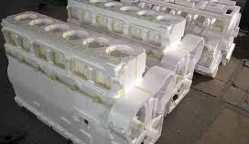
The HT250 transmission case (816mm × 530mm × 578mm) presents significant casting challenges due to its:
- Wall thickness variation: 14-50mm
- Complex internal structures
- High dimensional accuracy requirements
Key process parameters were calculated using fundamental casting equations:
Gating system design follows the continuity equation:
$$ Q = A \cdot v = \text{constant} $$
Where Q = flow rate (m³/s), A = cross-sectional area (m²), v = flow velocity (m/s)
2. Comparative Analysis of Three LFC Schemes
| Parameter | Scheme 1 | Scheme 2 | Scheme 3 |
|---|---|---|---|
| Pouring position | Horizontal top-gating | Inclined side-gating | Vertical top-gating |
| Runner size (mm) | 40×20 | 60×55 | 45×50 |
| Ingate size (mm) | 40×7.5 | 55×15 | 60×15 |
| Simulated defects | Shrinkage (8%), slag inclusion | Minor cold shut | Severe turbulence |
| Yield rate | 72% | 85% | 68% |
3. Numerical Simulation Optimization
The optimized Scheme 2 demonstrates superior performance through modified gating design:
$$ t_{\text{filling}} = \frac{V}{n \cdot A_{\text{gate}} \cdot v_{\text{optimal}}} $$
Where:
V = 0.285m³ (cavity volume)
n = 4 (number of ingates)
Agate = 825mm²
voptimal = 1.2-1.5m/s
Solidification analysis using Chvorinov’s rule:
$$ t_s = k \left( \frac{V}{A} \right)^2 $$
Where k = 0.8-1.2 min/cm² for HT250
4. Critical Process Parameters
Key controlled parameters in lost foam casting implementation:
| Process Stage | Parameter | Value |
|---|---|---|
| Pattern Making | EPS density | 25±1g/L |
| Steam pressure | 0.45-0.6MPa | |
| Cooling water | ≤40°C | |
| Coating | Viscosity (1st coat) | 69-71°Bé |
| Drying time | ≥12h @50°C | |
| Casting | Pouring temperature | 1,490-1,510°C |
| Vacuum pressure | 5.5-6.0kPa | |
| Pouring time | 90±10s | |
| Shakeout time | ≥20min |
5. Quality Validation
Dimensional verification showed excellent agreement between castings and CAD models:
$$ \Delta_{\text{max}} = \frac{|D_{\text{actual}} – D_{\text{model}}|}{D_{\text{model}}} \times 100\% < 0.8\% $$
Mechanical properties met specifications:
- Hardness: HB180-190
- Tensile strength: 255-265MPa
- Microstructure: Type A graphite (85-90%), pearlite matrix
6. Technical Advantages of Lost Foam Casting
The developed LFC process demonstrates significant benefits:
$$ C_{\text{saving}} = (M_{\text{sand}} \cdot P_{\text{sand}}) + (t_{\text{process}} \cdot L_{\text{labor}}) $$
Where:
Msand = 5.2t saved per ton casting
Psand = $85/t disposal cost
tprocess = 3.2h/t time reduction
Llabor = $25/h labor cost
This optimized lost foam casting solution provides a competitive manufacturing approach for complex thin-walled components, achieving dimensional accuracy within CT10 grade while maintaining defect rates below 2.5%.