The bed body is an important component of large machine tools, which carries the load of other parts of the machine tool and is also the core skeleton of the machine tool. Its quality has a direct impact on the accuracy, performance, and service life of the machine tool. As a large-scale casting, the oil tank part of the box type bed machine tool casting is the lifeblood of this product. In the thin-walled oil tank part, defects such as poor core support fusion and choking holes are prone to occur. After the product is tested for leakage, oil leakage occurs, and severe defects can lead to the casting being scrapped. Taking a certain bed machine tool casting produced by ZHY Casting as the research object, a reasonable casting process was determined through process improvement to address the quality issues that occurred in the early stage.
1.Structure and quality requirements for box type bed machine castings
The specific structural diagram of the box type bed machine tool casting is shown in Figure 1. The material is HT300, and the weight of the box type bed machine tool casting is 2989 kg. The contour dimensions of the product are: 3100 mm x 1265 mm x 785 mm. The main wall thickness of the box type bed machine tool casting is 15mm, with a maximum wall thickness of 90mm and a minimum wall thickness of 15mm. Box bed machine tool castings are required to have no defects such as sand inclusion, air holes, slag inclusion, and cold shuts on the processing surface. The oil chamber must not have defects, and the hardness of the guide rail must be greater than 183HBN. Quality problems such as loose organization and unqualified hardness are not allowed. Other appearance surfaces must not have obvious defects such as sand holes, sand sticking, and bulges that affect the appearance quality.

2. Analysis of original process and casting quality issues
2.1 Original process
In response to the technical quality requirements for box bed machine tool castings, we have adopted a process method of punching the guide rail surface downwards, with the bottom and oil tank surface facing upwards. At the same time, the box bed machine tool castings are all placed on the upper box surface, and a filter screen is placed under the transverse sprue to reduce the entry of impurities and other impurities into the mold cavity. The inner sprue is introduced from the guide rail surface and important machining surface, so that the iron enters the mold cavity steadily and evenly, thereby ensuring the stability of the inner cavity sand core, Convenient for size control and also beneficial for feeding and shrinking the riser.
(1) Melting parameters
| Types of raw materials | Pig iron | Machine iron | Scrap steel | Carburizing agent | Ferrosilicon ferromanganese | Proportions |
| Proportions | 5% | 35% | 60% | 2.0% | 0.7% | 0.4% |
The raw material ratio is shown in Table 1. At the same time, by adjusting the composition of the original molten iron, the control range of the main components meets the requirements of Table 2. The melting temperature of molten iron shall not exceed 1380 ℃, the overheating temperature shall be 1490-1510 ℃, and the pouring temperature shall be controlled between 1370-1390 ℃. Using a secondary incubation tank for incubation treatment, the inoculant is 0.5% SiFe (particle size 3-10 mm). During pouring, 0.1% SiFe (with a particle size of 3-10 mm) is added to the package for floating silicon inoculation, ensuring that the Si content of the box bed machine tool castings is controlled between 1.7% and 1.8%, and the C content is controlled between 3.05% and 3.15%.
| Chemical composition | C | Si | Mn | P | S | Ti | Pb |
| Proportions | 3.12 ± 0.03 | 1.40 ± 0.03 | 0.65 ± 0.03 | ≤ 0.04 | 0.08~0.12 | ≤ 0.030 | ≤ 0.0015 |
(2) Pouring system
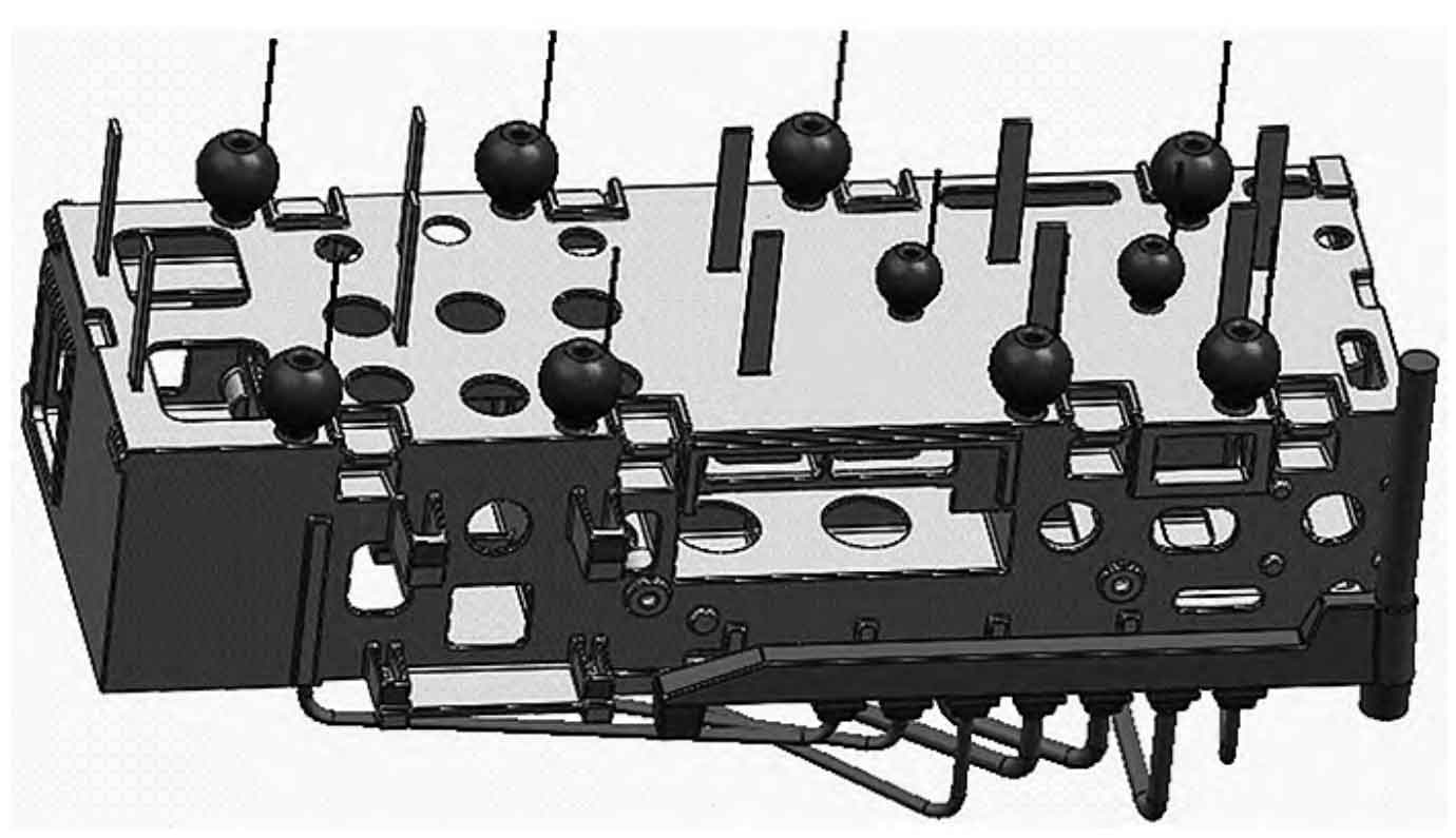
Adopting an open and bottom return pouring system, the inner pouring channel is introduced from the bottom, and the specific layout is shown in Figure 2. The pouring system ratio is: Σ F straight: Σ F horizontal: Σ F inner=1:1.56:1.53, with a vertical sprue ø 90 mm, a horizontal sprue (105 mm+84 mm) x 105 mm, and an internal sprue ø 35 mm x 4/ø 50 mm x 3 (ø 35 cross-sectional area 3848 mm2, ø 50 cross-sectional area 5890 mm2). The process adopts 8 S100mm and 2 S80mm ball risers, without placing cold iron.
2.2 Quality issues with box bed machine tool castings
(1) According to the above process, 13 box bed machine tool castings were produced, and 4 of them had a hardness of 164-176 HBN, which was lower than the customer’s requirements. Through metallographic testing, it was found that the pearlite content was only 80%~90%. Other products with qualified hardness also had a concentrated hardness of 180-185 HBN, which poses a relatively high risk.
(2) The box type bed machine tool castings produced have a lot of sand inclusions on the box surface, and almost every piece needs to be repaired by welding, which increases the difficulty of subsequent cleaning and repair costs.
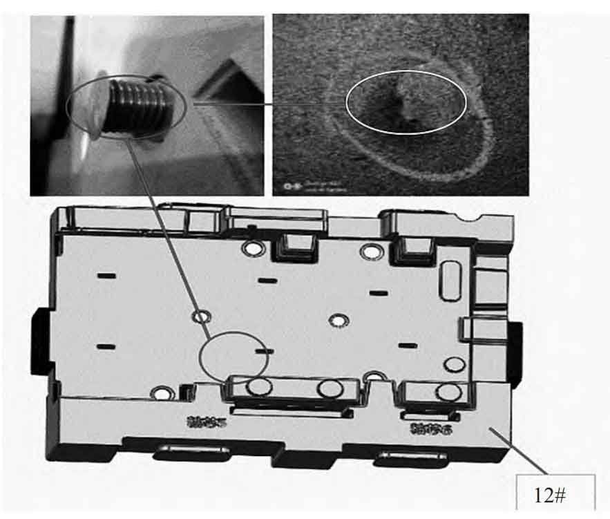
(3) According to the above process, severe choking occurred during the pouring process, and 7 pieces were scrapped due to choking, resulting in a waste rate of 53.8%. The photo of the box type bed machine tool casting after choking is shown in Figure 3. The circled areas indicate the specific choking and poor fusion of the core support. After welding repair, the PT test was found to be unqualified.

2.3 Cause analysis
(1) The material of the box type bed machine tool casting is HT300. Due to the large deviation in wall thickness, slow pouring and relatively low pouring temperature, under an open pouring system, the box type bed machine tool casting is prone to defects such as cold shut, loose structure, and inadequate hardness. Due to structural reasons, the quality of other products poured with the same material of molten iron is relatively stable, but there is a quality issue of unqualified hardness on this product. Insufficient amount of pearlite is likely due to insufficient content of chemical elements that promote the formation of pearlite, and high CE values also promote the formation of ferrite.
(2) The problem of sand inclusion on the upper box surface is mainly due to the fact that the upper box surface is flat, the gap between the lower core is small, and the control of the sand core coating layer is not good. During the lower core process, sand is rubbed against the upper box surface, and there is less overflow and riser on the upper box surface, which easily leads to slag inclusion after pouring. Secondly, due to the special casting structure of the box type bed machine tool, the weight reduction holes and threading holes on the upper box surface are concentrated at one end, and there are almost no weight reduction holes on one side of the oil tank. In the actual production process, a lot of core supports are used, which makes it easy to rub against sand when placing the core. Poor cleaning of loose sand leads to sand inclusion in the castings of the box type bed machine tool.
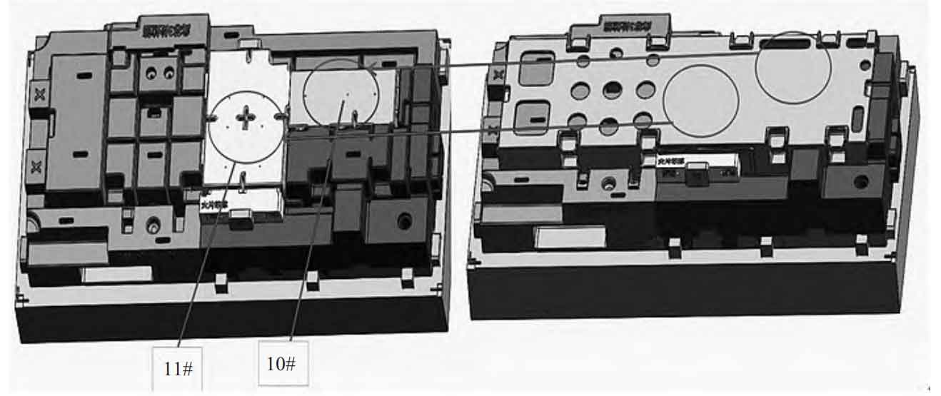
(3) The problem of choking during pouring tends to occur at the 10 # and 11 # core positions, as shown in Figure 4. The lower side of the 10 # and 11 # cores is fixed by the core head, while the upper side is completely supported and fixed by the core support. The contact surface is large and cannot be effectively fixed. These two sand cores are prone to shaking and causing choking under the impact of molten iron.
(4) After using ordinary core braces, poor fusion occurred. Due to excessive pouring during pouring, the pouring temperature could not be effectively guaranteed, resulting in poor fusion of core braces, as shown in Figure 5.
3. Process improvement measures and results
3.1 Improvement measures
(1) Improvement of smelting process
Due to the beneficial effect of increasing the proportion of scrap steel on the hardness of box bed machine castings, the proportion of scrap steel was appropriately increased during the melting and batching of molten iron; In order to ensure the content of pearlite, the control median of Mn was increased from 0.65% to 0.95%, the control median of C was reduced from 3.12% to 3.07%, and the control median of Si was reduced from 1.75% to 1.71%; The pouring temperature is adjusted to 1380-1400 ℃, while other melting parameters remain unchanged.
(2) Improvement of casting process
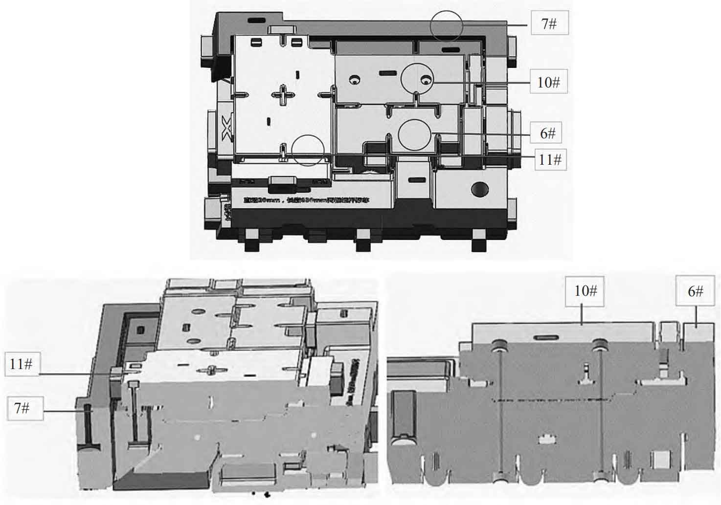
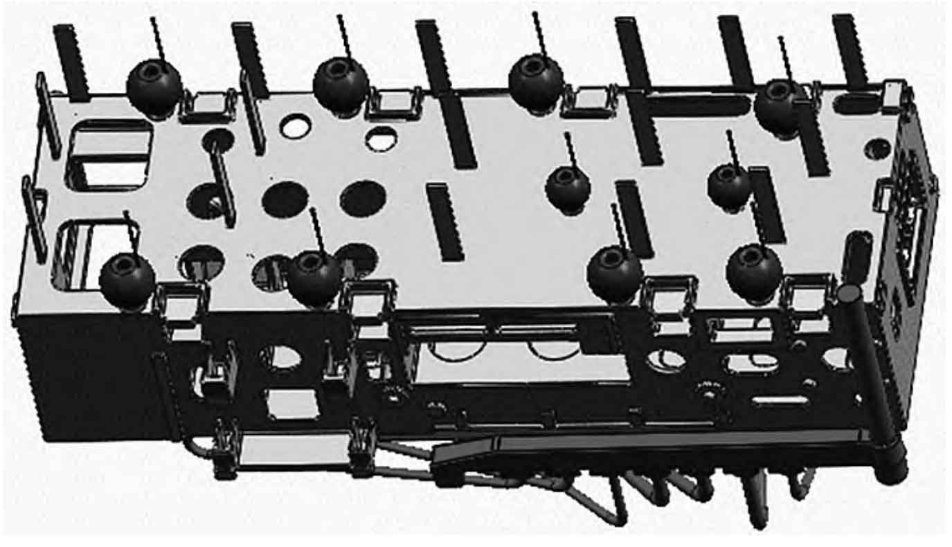
Due to the special structure of the casting of this box type bed machine tool, the original 3D process used a lower core and top surface support method, which made it difficult to effectively fix the 8 # and 11 # sand cores. The 12 # core was fixed to the 8 # and 11 # sand cores by pressing the core support, which could not completely solve the problem of choking caused by the shaking of the sand cores during pouring. At the same time, it is easy to rub the sand and cause the box type bed machine tool casting to scatter sand. In order to completely solve the problems of choking and poor fusion of sand core support, this product is directly modified to be produced using 3D printing core marking method. The sand core is produced using the “standard core method”, and the heads of the 8 # and 11 # sand cores that are difficult to fix are designed as pre embedded screw methods. Before lowering the core, the 6 # core and the 10 # sand core are connected and fixed together through screws. The 7 # sand core is first pre embedded with two benchmarks with a length of ø 20mm and 650 mm, and the 11 # core is fixed through the 7 # sand core screw. Reduce the use of core supports through core labeling, as shown in Figure 6. Adjust the gap between the remaining sand cores from 1 mm to 1.5 mm. The number of overflow risers on the upper box surface has increased from 10 to 16, resulting in an additional outlet area of 5850 mm2, as shown in Figure 7. After adopting the 3D printing core technology, the production cost has been significantly reduced, the process operation is simple, the quality of box bed machine tool castings has been effectively guaranteed, and on-site production efficiency has been significantly improved. At the same time, due to the high precision and good surface quality of 3D printing sand cores, moderate gaps in the core assembly process, small skin gaps in the box type bed machine tool castings, the appearance quality of the box type bed machine tool castings has been significantly improved.
3.2 Improvement Results
According to the above improved process, 40 pieces of this product were continuously produced. The pearlite content in the matrix structure of the box bed machine tool castings was ≥ 95%, with a tensile strength of 315~335 MPa and a solid hardness of 183~192 HBN, meeting the quality requirements of customer materials. At the same time, the pouring process is smooth, and there is no choking phenomenon at the pouring temperature of 1380-1400 ℃. The box bed machine tool castings do not have defects such as slag inclusion, sand inclusion, and poor fusion of core supports. The improvement effect is very obvious, and the scrap rate is controlled below 1.5%.
4. Conclusion
The production of box body machine tool castings has its unique features. After a long period of exploration, a set of production processes for thin-walled box castings of oil tanks has been gradually summarized and applied in production practice. The main content includes: the process adopts a non top core support at the oil tank, the box type bed machine tool castings are all placed on the upper box, and a filter screen is placed under the transverse runner; In order to ensure the content of pearlite, the content of Mn, C, and Si is strictly controlled; Ensure that the pouring temperature is above 1380 ℃, and the box can only be lifted and packed after 72 hours.
