
The transition of a critical hub component from conventional sand casting to lost foam casting presented a significant technical challenge. The component, specified in ductile cast iron grade QT500-7, required a hardness range of 170-230 HB after normalizing and tempering, with an elongation of at least 7%. Its substantial mass of 120 kg and an average wall thickness of 12 mm, featuring localized thicker sections, inherently predisposed it to shrinkage porosity and cavity defects during solidification. The primary objective was to redesign the casting process for the lost foam environment to eliminate these defects while meeting all mechanical property specifications.
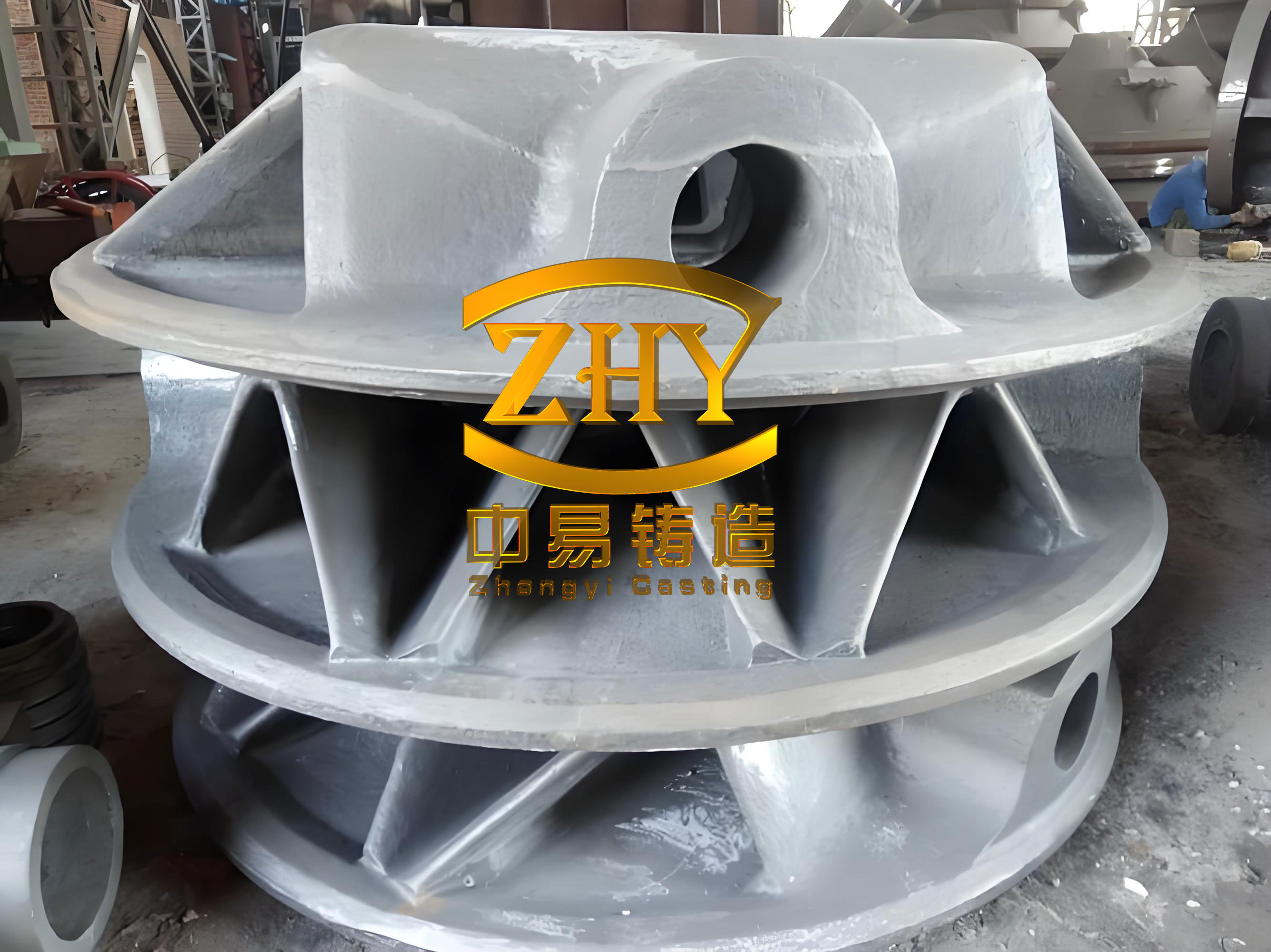
The initial analysis focused on the component’s geometry, which is a rotationally symmetric part with a large open face. For lost foam casting, the orientation during sand filling is paramount. The only feasible position was with the large open face upward to ensure complete and uniform compaction of the unbonded sand around the complex pattern. This fixed orientation became the constraint for all subsequent gating and risering design.
Comprehensive Gating System Analysis and Design
Four distinct gating locations were conceptually evaluated, each with its own set of fluid dynamics and thermal consequences for the solidifying ductile cast iron.
| Gating Location | Key Advantages | Critical Disadvantages | Feasibility for Ductile Iron |
|---|---|---|---|
| Top (Open Face) | Direct feeding to potential hot spots. | Severe back-pressure and violent pyrolysis gas counterflow, leading to turbulence and possible blows. Slow metal confluence causing cold shuts. | Poor – High risk of defects and unsafe casting practice. |
| Mid-Flange Outer Perimeter | Stable filling of lower sections. | Long flow path leads to premature cooling at the far end. Creates a reverse temperature gradient, isolating the top section as a thermal hot spot with inadequate feeding. | Conditional – Top section prone to shrinkage. |
| Mid-Inner Perimeter (Bore) | Shorter, more controlled flow paths. Promotes directional solidification towards the top open face. | The top central region remains the last to solidify and requires explicit feeding. | Good – Defects localized to a feedable area. |
| Bottom | Quiet, progressive filling. | Creates the worst thermal gradient for feeding thick sections. Thin internal features impede flow, increasing mistun risk. | Poor – High risk of distributed shrinkage and mistuns. |
Based on this analysis, the Mid-Flange Outer Perimeter and Mid-Inner Perimeter schemes were selected for experimental trials, as both had the potential to localize the shrinkage problem to the top, riser-accessible region of the ductile cast iron casting.
Theoretical Foundation for System Sizing
The gating system was designed using fundamental hydraulic principles. The initial step involved calculating the required choke area at the ingate using a modified Bernoulli’s equation, often applied in the form of the Ozan’s formula for cast iron:
$$A_g = \frac{W}{\rho \cdot t \cdot C_d \cdot \sqrt{2g \cdot h_l}}$$
Where:
$A_g$ is the required choke area (mm²),
$W$ is the casting weight (kg),
$\rho$ is the density of liquid ductile cast iron (~7000 kg/m³),
$t$ is the desired fill time (s),
$C_d$ is the discharge coefficient (accounting for system turbulence and friction, further reduced to ~0.6 for foam pattern decomposition),
$g$ is acceleration due to gravity (m/s²),
$h_l$ is the effective metallostatic head (m).
For a heavy-section casting like this hub, a fill time of approximately 45-50 seconds was targeted to balance turbulence and heat loss. The area ratios for the gating system were selected as 1.5 (Sprue) : 2 (Runner) : 1 (Ingate) to ensure a pressurized, non-aspirating system that promotes rapid filling. Applying these ratios, the calculated ingate choke area was determined to be approximately 2450 mm² for the outer perimeter scheme.
The number of ingates is critical. Too few create long flow paths and hot spots; too many cause chaotic metal confluence and turbulence. For the outer perimeter scheme, 4 ingates were placed, dividing the circumference into quadrants, resulting in an individual ingate area of ~700 mm². For the inner perimeter scheme, 4 ingates were also used, requiring a total area of ~2820 mm² to account for the slightly different flow dynamics.
Risering and Feeding Strategy
Given the fixed top-heavy orientation, the top open face was the inevitable thermal center. Riser design is governed by the requirement that the riser must solidify after the casting section it feeds. The required riser volume can be estimated from the solidification shrinkage of ductile cast iron, typically 4-6%. The modulus method is a key tool here.
The modulus (Volume/Surface Area ratio) of the suspected hot spot must be calculated. For a cylindrical top section, the modulus $M_c$ is:
$$M_c = \frac{V}{A} = \frac{\pi r^2 h}{2\pi r^2 + 2\pi r h} = \frac{rh}{2(r+h)}$$
A riser’s modulus $M_r$ must satisfy $M_r > 1.2 \times M_c$ to ensure directional solidification. For the inner perimeter gating, four cylindrical risers with a bottom contact diameter of 40 mm and a height of 120 mm were designed. Their modulus was verified to be greater than that of the top hub section, ensuring they remained liquid to feed the solidification shrinkage of the ductile cast iron. For the outer perimeter scheme, ten smaller rectangular risers were used in an attempt to distribute feeding points.
Experimental Procedure and Results Analysis
Trial 1: Comparative Evaluation
Three castings were produced with each gating scheme. Key process parameters were held constant: Pouring Temperature: 1480-1500°C, Vacuum Level: -0.06 to -0.08 MPa. The variation was in pressure hold time (8, 9, 10 min).
| Gating Scheme | Surface Quality | Defect Location (upon sectioning) | Conclusion |
|---|---|---|---|
| Mid-Flange Outer Perimeter | Severe fold defects diametrically opposite ingates. Minor sand adhesion. | Shrinkage porosity at ingate junctions and the opposite flange region. | Unacceptable. Unstable fill and poor thermal gradient. |
| Mid-Inner Perimeter (4 gates) | Clean surface, no folds. | No shrinkage in lower 2/3 of casting. Minor isolated porosity in top center, contained within riser feed zones. | Acceptable. Sound casting body; top defects removable. |
The failure of the outer perimeter scheme can be analyzed through solidification theory. The gates introduce heat locally, creating isolated hot spots. The long flow path allows the metal at the far circumference to cool significantly, failing to establish a strong thermal gradient toward the central risers. The solidification fronts likely pinned, isolating liquid pools that subsequently shrank.
Trial 2: Process Parameter Optimization for Inner Perimeter Gating
With the successful gating scheme identified, the focus shifted to refining parameters to eliminate sand adhesion and ensure consistency. Nine castings were produced using the 4-point inner perimeter gate design. The pouring sequence was “slow-fast-slow” to initially establish a calm metal advance, rapidly fill the mold, and then top up the risers.
The vacuum level was critically examined. While necessary to remove pyrolysis gases, excessive vacuum increases sand compactness and permeability, leading to metal penetration and sand adhesion. The optimal range was confirmed at -0.06 to -0.08 MPa. A hold time of 8 minutes was sufficient for complete solidification of the thick-section ductile cast iron part without causing mold wall collapse or unnecessary cycle time. The final, optimized parameters are summarized below:
| Process Parameter | Optimized Value / Range |
|---|---|
| Gating Design | Mid-Inner Perimeter, 4 ingates |
| Riser Design | 4 cylindrical top risers |
| Pouring Temperature | 1480 – 1500 °C |
| Mold Vacuum | -0.06 – -0.08 MPa |
| Fill Time | 46 – 50 seconds |
| Pressure Hold Time | 8 minutes |
| In-Mold Treatment Time | 9 – 10 minutes |
Metallurgical Control of Ductile Cast Iron Properties
Achieving the specified QT500-7 properties in a thick-walled casting requires precise chemical composition control to manage the microstructure, particularly the matrix ferrite/pearlite ratio, which governs strength and elongation.
The carbon equivalent (CE) must be high enough to ensure good castability and graphitization potential but controlled to prevent excessive graphite flotation in heavy sections. Silicon is a key ferritizer and promotes graphite formation. Manganese stabilizes pearlite. Copper was added as a pearlite promoter to achieve the required strength without excessively raising manganese levels, which can segregate to cell boundaries and embrittle the ductile cast iron. The target composition was established as follows:
| Element | Target Range (wt.%) | Metallurgical Role |
|---|---|---|
| Carbon (C) | 3.4 – 3.8 | Base for graphite formation, fluidity. |
| Silicon (Si) | 2.4 – 2.8 | Ferritizer, graphitizer, strengthens matrix. |
| Manganese (Mn) | 0.35 – 0.50 | Pearlite promoter, solid solution strengthener. |
| Phosphorus (P) | < 0.08 | Minimized to prevent phosphide eutectic embrittlement. |
| Sulfur (S) | < 0.03 | Minimized to reduce Mg consumption during treatment. |
| Copper (Cu) | 0.30 – 0.35 | Controlled pearlite promoter, improves strength uniformly. |
The nodule count and shape (spheroidization) are vital for ductility. A high-yield, low-impurity magnesium-ferrosilicon treatment alloy was used with an efficient inoculation practice. The extended in-mold treatment time of 9-10 minutes was crucial for this thick casting, allowing the post-inoculation fading effects to be minimized within the central sections of the solidifying ductile cast iron.
The final heat treatment (normalizing and tempering) refined the as-cast microstructure, ensuring a consistent ferrite-pearlite matrix throughout the heavy section, which delivered the guaranteed mechanical properties: Hardness: 170-200 HB, Elongation: 7-10%, and a consistent graphite nodularity rating of 1-2.
Conclusion
The successful production of a thick-walled QT500-7 ductile cast iron hub via lost foam casting was achieved through a systematic engineering approach. The critical factors were:
- Gating Strategy: The selection of a mid-inner perimeter, four-point gating system established a favorable thermal gradient, directing the major solidification front toward the top of the casting where it could be effectively managed by strategically placed risers.
- Integrated Process Control: The synergy between moderate vacuum levels, controlled fill time, and sufficient pressure hold time was essential to produce sound castings free from gas-related defects, sand adhesion, or shrinkage.
- Metallurgical Precision: A carefully balanced chemical composition, coupled with effective nodularizing and inoculation treatment, ensured the desired ferrite-pearlite matrix was achieved consistently throughout the heavy section, meeting all specified mechanical property targets for the ductile cast iron component.
This case demonstrates that for challenging heavy-section ductile iron castings, lost foam technology is not merely a pattern replacement process. It requires a holistic redesign based on the unique interplay of foam pyrolysis, unbonded sand mechanics, and the solidification science of ductile cast iron to achieve defect-free, high-integrity components.