
The turbocharger turbocharger is a high-speed rotating component with a complex curved surface structure. In order to improve the turbocharging efficiency, not only does it require high precision in blade shape values, but also high reliability. For large-sized high-temperature alloy turbine castings, there are generally problems such as poor manufacturing accuracy and unstable performance, especially for turbine castings with an overall diameter greater than 300 mm. Due to the long solidification time of the wheel hub, there is also a problem of performance degradation caused by coarse grains. By conducting simulation optimization of turbine casting process and combining it with rotational fine-grained process, defects such as shrinkage pores, porosity, inclusions, porosity, and cracks can be obtained, as well as turbine castings with dimensions and performance that meet the requirements.
1. Structural characteristics of turbine castings
The large-sized turbine has a contour size of approximately 400 mm x 240 mm, consisting of a trapezoidal thick hub with dimensions of approximately 220 mm/approximately 120 mm x 202 mm, and 12 free form curved blades with a length of 118 mm wrapped around the surface of the hub. The blades are distributed radially and are long and thin. The main difficulties are as follows:
(1) The material of the turbine is high-temperature alloy K418B, which is a nickel based precipitation hardening equiaxed crystal turbine casting high-temperature alloy. The alloy contains a large amount of easily oxidizable elements Cr, Al, Ti, and needs to withstand high centrifugal force and vibration loads during operation, as well as exhaust gas temperatures up to 750 ℃. It has high requirements for strength, impact, fatigue, and durability. The turbine castings must not have defects such as pores, cracks, shrinkage, and porosity.
(2) Compared with the previous turbine, this turbine has a larger size and requires higher stability in blade size. The surface profile is the same as the previous small-sized turbine, both requiring 0.8 mm. The dimensional tolerance corresponds to the requirements of CT6 level in the dimensional tolerance of GB/T 6414 turbine castings.
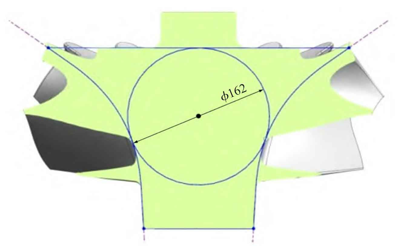
(3) The thickness of the thinnest blade in the turbine casting is only 1.8 mm, and it is located at the maximum outer circle, making it difficult to form. The maximum diameter of the hot spot circle in the center hub is 162mm (Figure 1), which easily leads to coarse grains and unqualified performance.
2. Analysis of Turbine Casting Process
In response to the material requirements of high-temperature alloys and the purity requirements of turbine castings, the mother alloy rod is first melted using a vacuum induction furnace, and then the parts are poured using vacuum remelting. This can reduce the oxidation, porosity, and inclusions of alloy elements, improve the purity of the alloy, and ensure the performance of turbine castings.
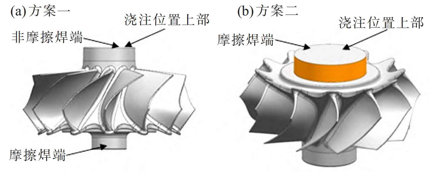
Analyzing the structure of the turbine casting, it was found that the turbine casting only has one geometric hot spot, with a diameter of approximately 162 mm (Figure 1), located at the center of the trapezoidal wheel hub. This area is thick and accounts for about 70% of the weight of the turbine, requiring a significant amount of shrinkage. A shrinkage riser must be installed. According to the literature, turbine castings generally adopt a center riser top pouring pouring scheme. After analyzing the structure and dimensions of the turbine casting, the riser can be set at the friction welding end or non friction welding end of the turbine casting. As shown in Figure 2, in general, to ensure the welding quality between the turbine and the turbine shaft, the end face used for friction welding is placed on the bottom surface.
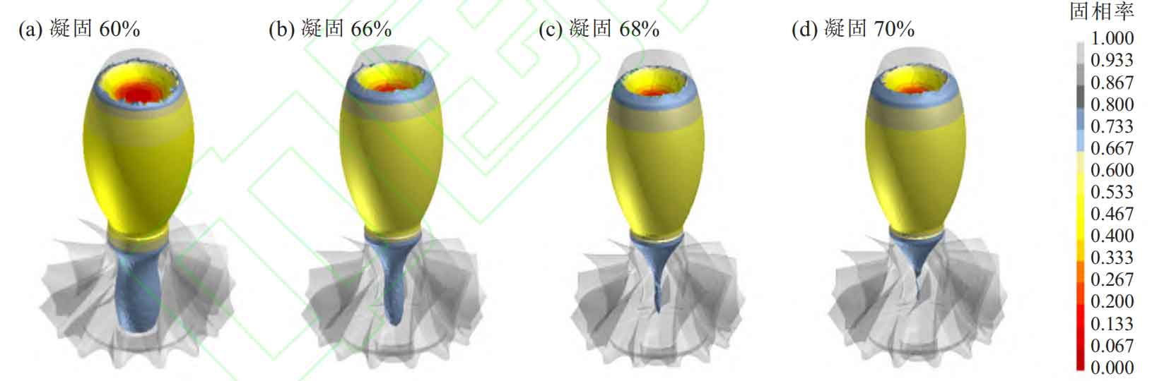
Using ProCAST software, simulation optimization was carried out on scheme one, and it can be seen that there is an isolated hot spot zone in the center of the turbine casting, forming shrinkage defects, as shown in Figure 3.
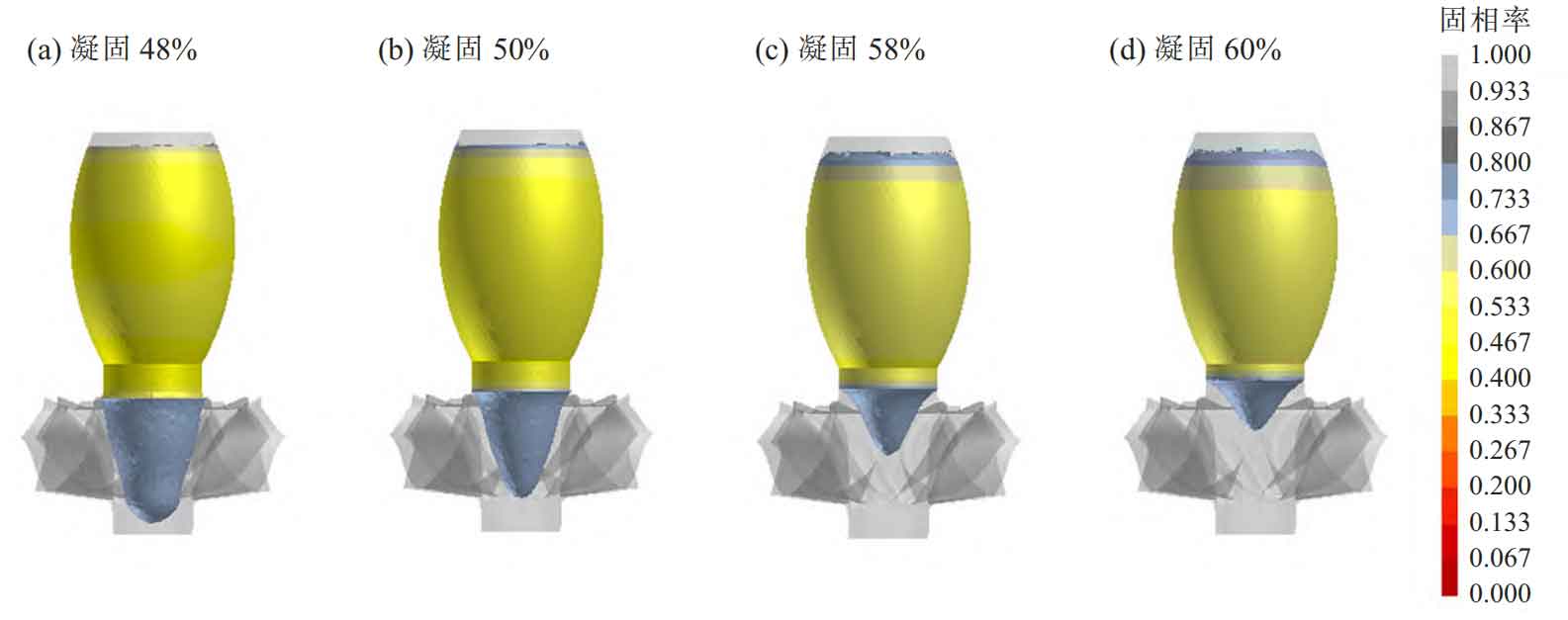
Scheme 2 (Figure 4) adopts the friction welding end face upwards. Due to the small size of the friction welding end face, it does not meet the required size of the riser neck. When setting up a riser at this location, it is necessary to artificially increase the outer diameter of the outer circle to reach the size of the riser neck (this area is the processing area), ultimately ensuring that the turbine casting solidifies in sequence to ensure shrinkage. The solidification simulation optimization of scheme 2 was carried out using ProCAST software. It can be clearly seen that during the solidification process, the turbine casting solidifies before the riser neck, and the riser neck solidifies before the riser neck, which can effectively achieve sequential solidification and ensure that there are no shrinkage cavities or porosity defects inside the turbine casting.
The selection of comprehensive shrinkage rate is crucial to ensure the dimensional accuracy of turbine castings. For investment casting, the shrinkage factors that affect the size of turbine castings include alloy shrinkage, mold material shrinkage, and shell expansion. Due to the significant difference in wall thickness of turbine castings, combined with previous experience in producing similar parts, the comprehensive scale for this turbine is selected as follows: axial scale reduction of 3.0%, radial scale reduction of 2.7%, and one piece should be prefabricated in advance during mold making compared to the turbine
A cold wax block with a center hub size of 5-7 mm smaller on one side is fixed in the mold to ensure the accuracy of the wax mold size.
Based on the preliminary determination of the process plan, a detailed design of the sprue and riser was carried out, and the specific dimensions of the riser neck and spindle shaped riser in Plan 2 were determined. Determine the selection of silica sol shell investment casting for turbine castings, and the pouring method is to use riser top pouring, with one piece for each type.
The common investment casting method usually causes overheating at the root of the riser of the turbine casting, resulting in coarse grain size in this area and a decrease in the strength of the main body. In the determined process plan, friction welding is required between the root of the riser and the connecting shaft after processing, which may cause the strength of the body to be lower than that of the weld seam. During the tensile test of the body after welding, fracture occurs on the turbine body. If a riser is installed on the end face at this end, fine grain casting is required to solve the problem of coarse grains in the casting at the root of the riser, and there are strict requirements for grain size in the technical requirements for turbine castings. Grain refinement must be carried out during production. Due to the large thickness of the wheel hub and riser in large-sized turbine castings, the required solidification time is long, and the use of conventional refining agents results in a decline phenomenon, making it difficult to achieve the grain refinement effect in the center of the turbine. To ensure the grain size at the center of the turbine hub, the process of forward and reverse centrifugal stirring is used to refine the grains at the center of the turbine, achieving grain refinement in thicker areas of the hub. After consulting materials and combining experimental verification, the adopted forward and reverse centrifugal stirring process for fine crystals is determined based on simulation calculation results, with a stirring speed of 150 r/min, a forward and reverse stirring time of 40 s, and a forward and reverse conversion time of less than 5 s.
3. Simulation analysis of turbine casting process
The final process plan was subjected to coupled simulation analysis of filling and solidification using ProCAST software (Figure 5). To ensure the filling of the blades, based on the liquidus temperature (1344.7 ℃) and solidus temperature (1235.7 ℃) of K418B alloy, the filling temperature is set to 1410 ℃, the flow resistance section is set to 40 mm, and the total filling time is 13 seconds.
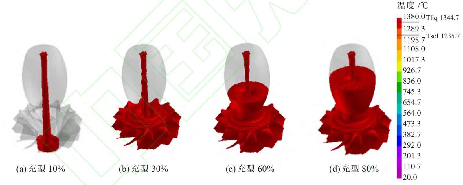
Through analysis, it can be seen that when the filling time is 4 seconds (30% filling), the blade part is fully filled, and then the riser part is filled. During the filling process, the pouring is smooth and there is no splashing, air entrapment, or insufficient pouring. As the filling process approaches completion, solidification begins to occur at the tip of the blade, indicating that the set pouring temperature is appropriate and the turbine casting can ensure complete filling.
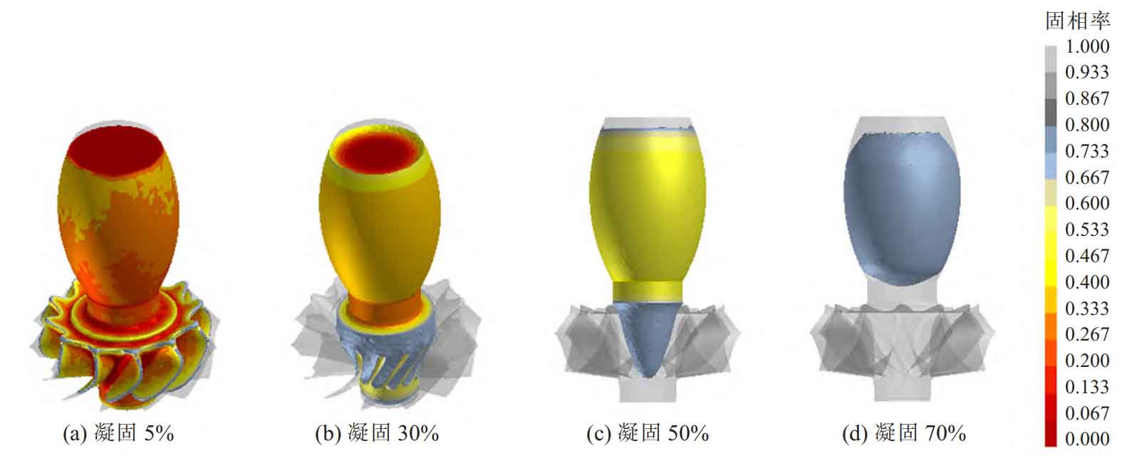
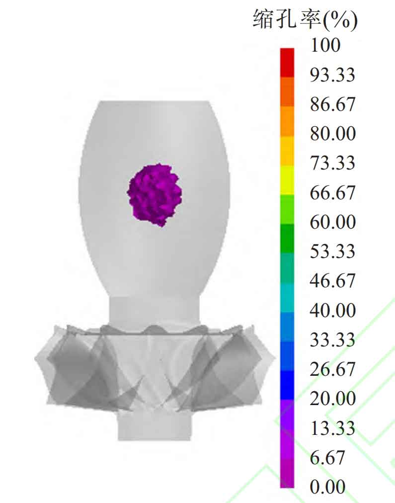
Through solidification analysis (Figure 6), it was found that the wall thickness at the tip of the turbine blade was thin, and solidification had already begun after pouring. The time to complete solidification at the turbine blade was 580 seconds, the time to complete solidification at the turbine casting body was 2965 seconds, and the time to complete solidification at the riser of the turbine casting was 5865 seconds. During the solidification process, the temperature distribution is uneven and there is a large temperature difference. The surface temperature is low, while the center and thicker parts are higher. The temperature at the riser is the highest. The distribution of temperature gradient in the radial direction increases from the blade tip to the blade root and then to the hub direction, while in the axial direction, it increases from the bottom to the riser direction; The solidification sequence is that the blade tip solidifies before the blade root in the radial direction, and the blade root solidifies before the hub; The axial direction solidifies sequentially from the bottom to the riser, and the final solidification occurs at the center of the riser. During the solidification process, there was no isolated liquid phase zone, which fully realized the sequential solidification of the turbine casting and ensured that there were no shrinkage and porosity defects in the turbine casting. The analysis results of shrinkage and porosity are shown in Figure 7.
4. Production validation
After completing the mold production and pouring system design, trial production will begin according to the conventional investment casting process, including mold making, shell making, shell baking, melting and pouring, cleaning and other processes. It should be pointed out that the centrifugal rotation of the mold can start as soon as the pouring starts (the rotation speed can be controlled at around 100 r/min), pour to 1/3 of the riser, and stop rotating to achieve centrifugal filling of the blades; After pouring is completed, let it stand for 3 minutes. After the blades have initially solidified, start rotating the mold in the forward and reverse directions according to the set parameters, stirring the metal liquid, and the total stirring time is not less than 45 minutes.
According to the above casting process, a total of 2 turbine blanks are produced in two furnaces, and the quality of turbine castings is stable. The non-destructive testing of composition, performance, surface, and size of turbine castings was carried out, and the results are as follows:
(1) Chemical composition and mechanical properties: all elements are within the required range; Sampling and analysis of the connection between the riser and the turbine body showed an average grain size of 4mm, and the mechanical properties of the sample met the requirements.
(2) Through non-destructive testing such as X-ray and ultrasound, the turbine blades and interior are found to have no defects such as pores, inclusions, shrinkage holes, and looseness; The surface has undergone penetration testing without excessive defects such as cracks and inclusions.
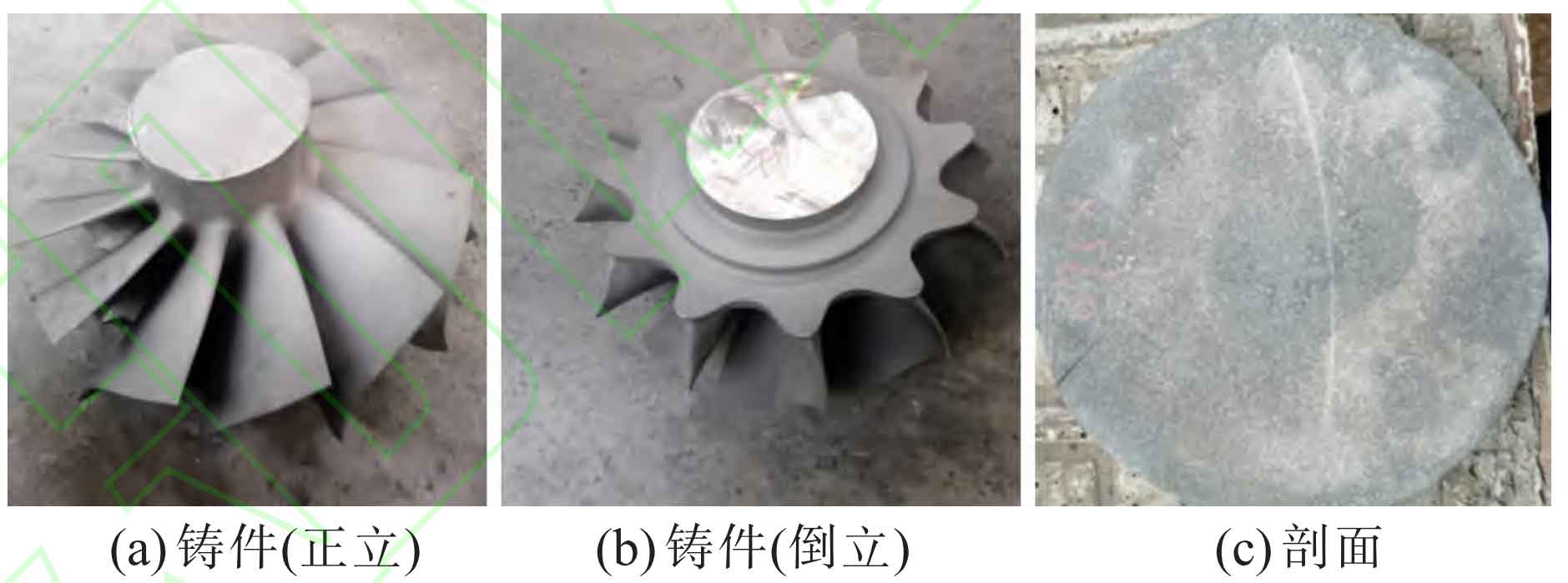
(3) The size detection uses a digital 3D scanning detector to scan the digital point cloud data of the turbine and blades, and then compares it with the required 3D model of the turbine casting blank. At the same time, key dimensions such as the thickness and surface profile of the blade blade position are measured and compared. The results show that the cast turbine size meets the requirements. The trial produced turbine is shown in Figure 8.
5. Conclusion
(1) Process design optimization was carried out on large-sized turbine castings using ProCAST software, resulting in the production of qualified large-sized turbine castings.
(2) For large-sized turbine castings, the casting process design with friction welding end facing upwards can be adopted, but relevant fine-grained casting process measures need to be adopted.
(3) To ensure the dimensional accuracy of turbine castings, the comprehensive shrinkage rate of the casting needs to use different axial and radial scales.