
The structure of the front-end box casting is complex, with many internal cavities, making the production of front-end box casting difficult. The main problems with front-end box castings are porosity and shrinkage defects, which affect the quality of front-end box castings. The concession rate and scrap rate of the front-end box castings account for the majority, and the complete qualification rate is relatively low. Through process improvement, the main optimization and adjustment of the mud core gas outlet and pouring system have been carried out, and the early porosity problem has been controlled. The quality of the front-end box castings has basically stabilized, meeting the requirements of large-scale production.
1. Structural characteristics and technical requirements of front-end box castings
The L21/31 front end box casting has a rough weight of 2180 kg and a contour size of 1800 mm x 1100 mm x 950 mm. Its internal structure is very complex, consisting of 27 sand cores in three layers, including upper, middle, and lower layers, forming multiple interrelated internal cavity structures. The distribution of clay cores in the cavity is shown in Figure 1. The main wall thickness of the L21/31 front end chamber casting is 12 mm, with a maximum wall thickness of 125 mm. The difference in wall thickness is significant, and casting defects such as porosity, shrinkage, and porosity are prone to occur, ultimately leading to leakage and scrapping of the front end chamber casting during water pressure and air pressure tests. The material of the front-end box casting is HT300, and the mechanical properties require tensile strength σ B ≥ 300 N/mm2, HB hardness 185-278

2. Existing problems and causes
The L21/31 front-end box has been in trial production since 2013, and there is a phenomenon of “suffocation” on the upper surface of the upper, middle, and lower layers. The air hole defects caused by the “suffocation” of the front end box casting are shown in Figure 2, which are not many in number, but have a large volume and smooth hole walls. They appear on the surface of the front end box casting and are mostly pear shaped, elliptical or circular in shape.

There are three main reasons for the occurrence of porosity defects:
1) From the analysis of the mechanism of invasive gas pores, it is mainly that when liquid metal enters the sand mold, the sand mold or sand core will produce a large amount of gas under the high-temperature action of the metal liquid. With the increase of temperature and gas volume, the pressure of gas at the metal casting interface continuously increases. When the pressure of local gas on the interface is higher than the external resistance, the gas will invade the liquid metal and form bubbles on the mold wall. After the formation of bubbles, they will detach from the mold wall and float into the liquid metal in the mold cavity. When bubbles do not have time to float and escape, they will form invasive pores in the metal.
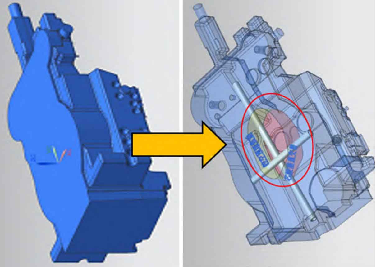
2) The previous pouring system had always arranged transverse runners on the upper box, and the inner runners were directly introduced to the bottom of the front box casting using ceramic pipes. Due to the height difference of the inner runner being close to 1000 mm, the molten iron achieves a higher flow rate in the vertical inner runner before entering the mold cavity. When it enters the mold cavity, the high-speed flowing molten iron is prone to curling up, and the gas in the mold cavity is easily trapped in the molten iron. The complex mold cavity structure is not conducive to the gas floating up. If the gas wrapped in the molten iron cannot float up and be discharged in time, In the end, most of them will stop moving on the surface or surface, eventually forming pore defects. Using software to simulate the filling process of molten iron, tracking the particle motion state as shown in Figure 3, there are obvious phenomena such as turbulence and entrainment.

3) Due to the complex structure of the L21 front-end box and the large number of mud cores in the mold cavity, the layout is mainly vertical, horizontal, and layered, which is not conducive to the gas release of the mud cores. In addition, the 24 # mud core in the upper part of the mold cavity (see Figure 1) has a large size (horizontal section size of about 1300 mm x 850 mm), which not only has a large gas generation capacity of the mud core itself, but also to some extent hinders the smooth gas release of the lower mud core and the fast gas release from the mold cavity.
3. Process improvement direction and process
Based on the above reasons analysis, propose a process direction to solve the surface and surface porosity defects of the L21 front-end box:
1) Resolve the impact of the mud core’s own gas release. The venting time of the mud core should be shortened to avoid the gas from the mud core moving out and entering the molten iron after the temperature of the molten iron drops and the molten iron fills the mold cavity, and there is no time to float up and discharge it.
2) Solve the impact of flying coils and unstable liquid level rise during molten iron filling.
According to the established process improvement direction, carry out front-end box casting process improvement.
3.1 Core Blowout
3.1.1 Increase the outlet area of 24 # mud core
The mud core has a large gas generation capacity. In order to ensure that the gas in the mud core is discharged as soon as possible during the heating process, and to minimize the intrusion of gas from the bottom and surrounding areas of the mud core into the molten iron, the center position of the top of the mud core is hollowed out through experiments and design discussions (ensuring that the sand consumption around the mud core is not less than 200mm), and pre buried back into the furnace coke. The advantage of doing this for the gas release from the mud core is to reduce the gas release from the mud core itself, leaving an outlet channel for the gas release from the mud core, and also increasing the storage space for the gas removed from the mud core, improving the tendency of the gas in the mud core to be discharged into the mold cavity, as shown in Figure 4.
3.1.2 Other mud core venting
After the experiment, the method of “pulling out the leather rope and embedding the ventilation rope” was adopted, as shown in Figure 5. When shaping the mud core, place a ventilation rope along the core bone (selected according to the size of the mud core) φ 6 mm φ After installing the core in the box, use a leather rope to lead the air outlet channel of the mud core from the core head to the outside of the sand box. After filling the sand, remove the leather rope. The advantage of doing this is that the ventilation rope is woven with nylon material, which has a certain toughness and strength. After the leather rope is pulled out, the mud core and the outside can form a stable air outlet channel. In addition, this method also reduces safety risks during the operation process and plays a certain role in preventing quality defects of air holes in the front-end box castings.

3.1.3 Setting of gas outlet and riser
The 24 # mud core is generally covered at the upper part of the mold cavity, which is not conducive to the discharge of gas from the mold cavity, and most of the locations where porosity defects occur are located at the lower part of the mud core. In order to allow the gas at the bottom of the mud core to be smoothly discharged from the inside of the mold cavity, an additional gas outlet should be added at the locations where porosity defects are common (areas where gas is prone to accumulate in the mold cavity). As shown in Figure 6, the riser passes through the 24 # mud core, allowing gas to be directly removed from the upper box outlet riser.

3.2 Improvement of pouring system
3.2.1 Improvement of the first pouring system
The improvement of the pouring system mainly aims to reduce the turbulence phenomenon during the filling of molten iron. After technical communication with the user, the transverse gate is placed at the bottom of the front box casting, and the slow flow effect of the horizontal transverse gate at the bottom is used to reduce the filling speed of molten iron at the inner gate.
Design a completely bottomed pouring system scheme based on the actual situation. As shown in Figure 7, the transverse runner is located at the bottom of the front box casting, buffering the molten iron in the longitudinal runner and reducing the filling speed. During the trial production period, based on the verification results, several small-scale improvements were made on this basic process foundation. After trial production, the number of porosity defects in the front box casting was significantly reduced by placing the transverse runner at the bottom, but it was not completely eliminated.

3.2.2 Improvement of the second pouring system
According to the analysis of the first experiment results, it is believed that the improved mud core gas outlet method is relatively reasonable, and the filling speed of molten iron has been slowed down. However, based on the quality results of the production of front-end box castings, the porosity defect has not been eliminated, so there is still room for process improvement. After communicating with FOSECO engineers, it is believed that a completely bottomed pouring design is helpful for the project improvement goals. In order to further reduce the phenomenon of molten iron turbulence and curling, and to maintain a smooth rise of the mold cavity liquid level as much as possible, it has been decided to apply filtering technology to add filter plates to the inner gate. This not only improves the filling speed, but also plays a role in blocking slag. Figure 8 is a schematic diagram of the filter casting system scheme.

4. Production validation
According to the improved and optimized core vent and bottom injection filter casting process plan, the molding and box configuration were carried out. After the casting was cleaned, the locations of common defects in the early stage were checked and confirmed, and the surface quality of the front box casting was good. After continuous production of 5 pieces, it was found that the surface quality of the blank was significantly improved, and the inner cavity wall was smooth without defects, with no air holes found. The surface quality of the front box casting is shown in Figure 9, indicating that good improvement results have been achieved.

5. Conclusion
1) By strengthening the mold and the air outlet, injection, and storage of the mud core, the orderly transfer of air from the mold cavity of the front end box casting and the mud core during the pouring process can effectively improve the porosity defects of the front end box casting and enhance the appearance quality of the front end box casting.
2) The front end box casting adopts the bottom injection open filter casting process, which can reduce turbulence during the casting process, make the filling process smooth, and at the same time reduce the gas entrapment of the metal liquid during the casting process, reducing the occurrence of porosity problems.