
In my experience with casting large engineering components, the production of spheroidal graphite iron castings, such as loader backseats, presents unique challenges when employing the V-process (vacuum molding). This method, while advantageous for surface finish and environmental benefits, often struggles with issues like mold wall movement, shrinkage porosity, and dimensional inaccuracies in thick-section spheroidal graphite iron parts. Here, I detail the comprehensive approach we developed to overcome these hurdles, ensuring the production of high-quality castings that meet stringent specifications.
The casting in question is a large loader backseat made from spheroidal graphite iron, equivalent to grade QT400-18. Its primary function is to serve as a counterweight in heavy machinery, demanding precise dimensions, minimal weight deviation, and controlled metallurgical properties. The casting measures approximately 3,195.6 mm in length, 1,352.55 mm in width, and 993.78 mm in height, with a mass of 5,906 kg. The wall thickness averages 120 mm, reaching up to 203 mm at certain sections, resulting in a high thermal mass that complicates solidification control. The U-shaped geometry further exacerbates risks of distortion during cooling. Key technical requirements include a fully ferritic matrix, graphite spheroidization level of grade 3, tensile strength of at least 400 MPa, elongation of 18%, and hardness between 149–187 HB.
The core difficulties in using the V-process for such large spheroidal graphite iron castings stem from the inherent variability in mold stiffness due to vacuum fluctuations. Unlike conventional sand molds, the V-process mold’s rigidity is dynamically dependent on maintained vacuum, which can lead to transient mold wall movement under the substantial graphite expansion pressures during eutectic solidification of spheroidal graphite iron. This movement promotes shrinkage defects and weight inconsistencies. Additionally, the sheer size of the casting exceeded the capacity of standard V-process lines, necessitating custom tooling. The handling and treatment of nearly 8 tons of molten spheroidal graphite iron also posed logistical challenges, as standard treatment ladles are typically smaller.
To address these issues, our strategy involved a multi-faceted redesign of tooling, gating, feeding, and processing parameters. The foundation was the creation of a specialized V-process flask. We designed and manufactured a super-sized flask with internal dimensions of 4,000 mm × 2,260 mm × 650/950 mm (height varying). Its structure incorporated dense, hollow ribs connected to the side vacuum chambers. These ribs were fitted with vacuum filter screens and contoured to follow the pattern shape with a 150–200 mm clearance. This design enhanced uniform vacuum distribution and structural rigidity, countering localized wall movement. The formula for estimating the critical vacuum pressure ($P_{vac}$) needed to resist metallostatic pressure and graphite expansion pressure can be expressed as:
$$ P_{vac} \geq \rho g h + \Delta P_{exp} $$
where $\rho$ is the density of molten iron (approximately 7,000 kg/m³), $g$ is gravity, $h$ is the effective metal height, and $\Delta P_{exp}$ is the pressure from graphite expansion, which for spheroidal graphite iron is significant and empirically derived.
The parting line was strategically placed to have the entire external profile formed in the drag half, with the sides built up using sand ramming techniques. This minimized parting line marks and simplified finishing. The gating system was designed as a semi-pressurized type to ensure rapid and tranquil filling, reducing turbulence and air entrapment. The gating ratio was carefully calculated as:
$$ \Sigma F_{sprue} : \Sigma F_{runner} : \Sigma F_{ingate} = 1 : 0.8 : 1.5 $$
This ratio promotes a controlled flow sequence. The total cross-sectional areas were sized based on the desired pouring time of 4.5–5 minutes for the total metal weight. The pouring time ($t_p$) can be related to the effective gating area ($A_g$) and metal head ($H$) by:
$$ t_p = \frac{W}{\rho \cdot A_g \cdot \sqrt{2gH}} $$
where $W$ is the casting weight.
For feeding the thick sections, we employed two inverted bottle-shaped open risers, each 200 mm in diameter and 500 mm tall, with neck dimensions of φ80 mm × 60 mm. To enhance their efficiency despite height constraints imposed by the flask, exothermic compounds were added to the risers during pouring. Additionally, nine vent risers (φ60 mm) were placed at strategic locations to aid in mold exhaust. A summary of the key casting design parameters is presented in Table 1.
| Parameter | Value or Specification |
|---|---|
| Casting Material | Spheroidal Graphite Iron (QT400-18) |
| Casting Mass | 5,906 kg |
| Average Wall Thickness | 120 mm |
| Maximum Wall Thickness | 203 mm |
| Flask Size (Custom) | 4,000 mm × 2,260 mm × 650/950 mm |
| Gating Ratio (Sprue:Runner:Ingate) | 1 : 0.8 : 1.5 |
| Number of Main Riser | 2 (Inverted bottle-shaped, φ200 mm × 500 mm) |
| Number of Vent Riser | 9 (φ60 mm) |
| Target Pouring Temperature | 1,320–1,340 °C |
| Target Pouring Time | 4.5–5 minutes |
| Molding Vacuum Pressure | |
| Mold Hardness |
The pattern was constructed from wood using 5-axis CNC machining for accuracy. Due to machine size limits, it was fabricated in two halves and then assembled. To combat distortion in the U-shaped geometry, reinforcing ribs were incorporated into the pattern, which also served as part of the runner system. This dual-function design helped maintain dimensional stability during cooling.
Melting and treatment of the spheroidal graphite iron were critical. We used a 12.5-ton medium-frequency induction furnace. The base iron chemistry was tightly controlled to provide a suitable foundation for spheroidization. The target compositions are summarized in Table 2.
| Element | Base Iron | Final Treated Iron |
|---|---|---|
| Carbon (C) | 3.6–3.7 | 3.4–3.6 (estimated) |
| Silicon (Si) | 1.5–1.6 | 2.7–2.9 |
| Manganese (Mn) | 0.2–0.3 | 0.2–0.3 |
| Phosphorus (P) | < 0.04 | < 0.04 |
| Sulfur (S) | < 0.03 | < 0.02 |
| Magnesium (Mg) | – | 0.03–0.05 |
| Rare Earth (RE) | – | 0.02–0.04 |
Given the lack of a single ladle for the entire treatment, we adopted a sequential approach. The molten iron was tapped at 1,480–1,490°C into preheated ladles. Spheroidizing treatment was conducted using the sandwich method in three separate 3-ton ladles, each processing about 2.6 tons of iron. For each batch, 40 kg of a 3-8 type spheroidizing alloy (Mg-Fe-Si with rare earths) and 21 kg of 75% ferrosilicon inoculant were used, covered with steel plates. The treated iron from all three ladles was then combined into a single 8-ton ladle for pouring. To prevent fade and enhance nodule count, a post-inoculation with 0.1% Incoude900 (a proprietary inoculant) was added during the pour via a stream inoculator. The kinetics of magnesium fade in large ladles can be modeled by a first-order decay equation:
$$ [Mg]_t = [Mg]_0 \cdot e^{-kt} $$
where $[Mg]_t$ is the magnesium content at time $t$, $[Mg]_0$ is the initial content, and $k$ is a rate constant dependent on temperature and slag conditions. Our rapid transfer and combined ladle approach minimized this time ($t$).
During pouring, which was maintained at 1,320–1,340°C, the exothermic compounds were added to the main risers when they were half-filled. The mold vacuum was kept above 0.06 MPa during both molding and pouring, with a sand compaction time of about 2.5 minutes to achieve a mold hardness over 90. This high rigidity was essential to withstand the expansion forces of the solidifying spheroidal graphite iron.
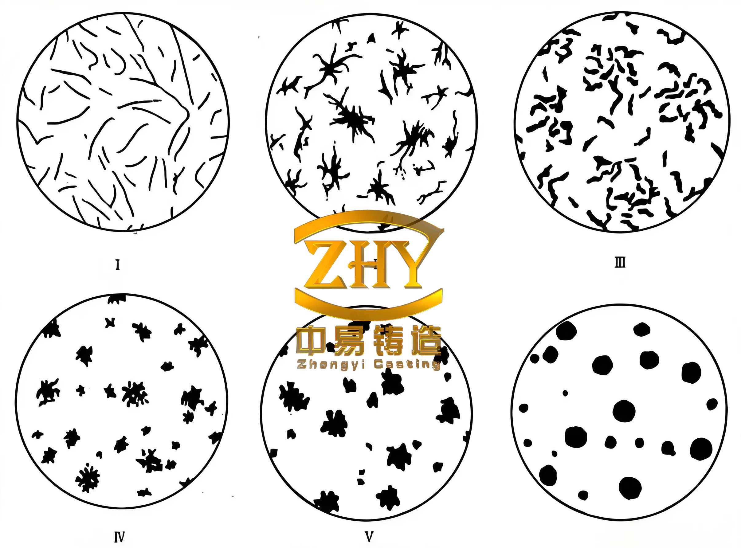
The results from batch production were highly satisfactory. The castings were free from macroscopic shrinkage cavities and porosity, and no gas defects affecting performance were observed. Dimensional accuracy was maintained, with the U-shape showing minimal distortion thanks to the pattern ribs. Surface finish was excellent, requiring minimal cleaning. The properties of separately cast keel blocks confirmed the quality: graphite spheroidization was at grade 3, with graphite size mainly at grade VI. The tensile strength averaged 490 MPa, elongation 19%, and hardness 180 HB, all meeting or exceeding the QT400-18 specification for spheroidal graphite iron. Compared to traditional green sand casting, the V-process implementation improved material yield by over 4% and reduced molding sand costs by more than 60%, alongside significant gains in productivity and working conditions.
In conclusion, the successful production of large spheroidal graphite iron castings via the V-process hinges on a holistic engineering approach. Key takeaways include: First, custom tooling design, particularly flasks with enhanced vacuum stability, is paramount to counter mold wall movement and ensure consistent rigidity for spheroidal graphite iron’s expansion. Second, a gating system that balances fill speed with tranquility, coupled with risers augmented by exothermic materials, effectively manages solidification shrinkage in thick sections. Third, meticulous control over metallurgy—from base iron composition through spheroidizing and multi-stage inoculation—is non-negotiable to achieve the desired microstructure and mechanical properties in spheroidal graphite iron. The mathematical relationship for solidification time ($t_s$) according to Chvorinov’s rule underscores the importance of modulus control:
$$ t_s = k \cdot \left( \frac{V}{A} \right)^n $$
where $V/A$ is the volume-to-surface area ratio (modulus), and $k$ and $n$ are constants. For spheroidal graphite iron, the value of $k$ is influenced by the graphite expansion, which can be harnessed for self-feeding if mold rigidity is sufficient. Finally, integrating process monitoring, such as online thermal analysis and vacuum control, ensures reproducibility. This case demonstrates that with tailored solutions, the V-process can be viably extended to heavy-section spheroidal graphite iron castings, unlocking its benefits for a broader range of industrial components.