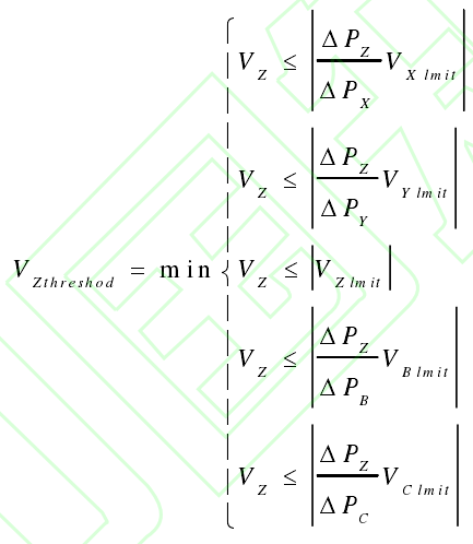
The z-axis is selected as the prospective control axis to verify the effect of five axis linkage speed control. Take the limit value of forward and reverse speed of each axis equal, set the electronic gear ratio and pulse frequency division of each axis servo driver respectively, so that the pulse equivalent of linear axis is 1 μ m and that of rotating axis is 0.001 °, that is, μ x, μ y, μ Z, μ B and μ C are all 1000. The calculation formula of z-axis forward looking velocity threshold can be further simplified as follows:
The maximum speed of X, y and Z linear axes is 2500 mm / min, and that of B and C axes is 1000 ° / min. According to the formula, the z-axis speed limit curve is calculated as shown in Figure 1. The minimum value of VZ is 1234.1 mm / min, which appears on the x-axis speed limit curve.
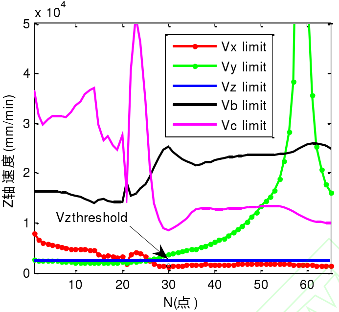
The prospective threshold of Z axis was set as vzthreshold = 1234.1mm/min. The speed limit of other axes can be cancelled or set to the maximum value allowed by the control system. According to the formula, only the maximum acceleration of z-axis will affect the number of forward-looking calculation time periods. The maximum acceleration of each axis is 757.3 mm / S2 when the forward looking control is not used and the programmed speed is f2500. The maximum acceleration of Z is set at 1500mm / S2, and the servo period is 5ms. According to the formula, when the z-axis look ahead control is obtained, the look ahead operation should be carried out 5 cycles in advance.
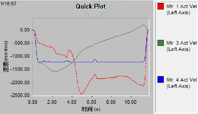
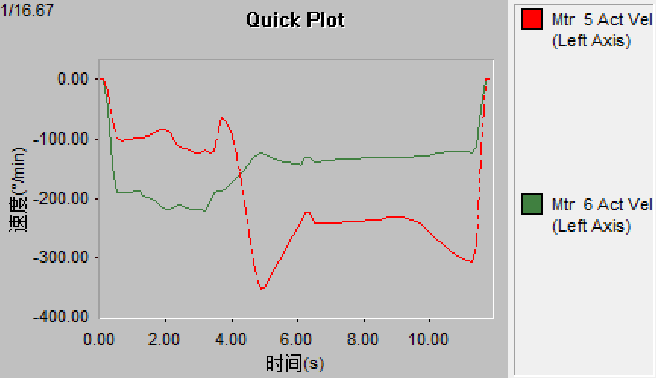
After the z-axis prospective control is started, run the impeller sand mold processing program, and collect the linear axis speed as shown in Fig. 2, and the rotation axis speed as shown in Fig. 3. The processing time was extended from 3.31 s to 11.4 s. It can be seen that in the case of overspeed, the look ahead control dynamically adjusts the time base by calculating in advance. Although the response time is sacrificed, the linear axis speed overrun part is calculated in advance, and the speed of each axis is limited within the expected limit. Among them, the maximum speed of x-axis is closest to the limit value. The speed fluctuation of each axle is obviously restrained and the equipment runs smoothly. It can be seen that through the single axis look ahead control of Z axis, the five axis linkage overall speed constraint control is realized.
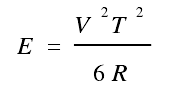
In the process of look ahead control, cubic spline is used to fit the inverse kinematics solution of discrete points, and the error E can be calculated according to the formula. Where V is the vector velocity in the forward direction, t is the operation period of RTCP, and R is the curvature radius of the trajectory.
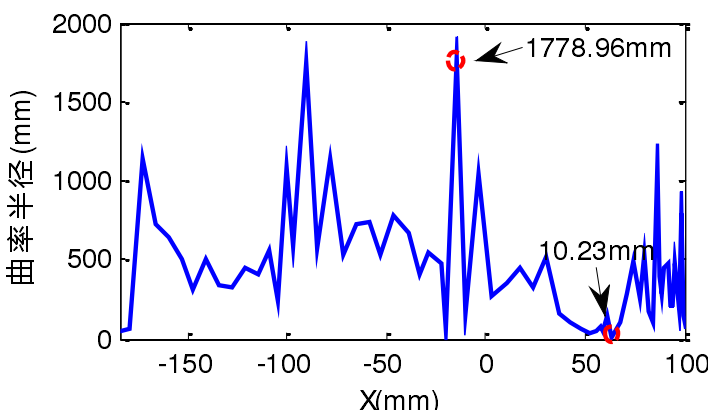
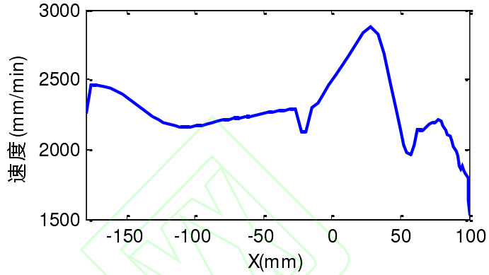
The reverse solution position of RTCP of x-axis, Y-axis and z-axis of impeller sand mold is calculated, and the spatial curvature radius r of running track is shown in Fig. 4. The maximum value of curvature radius is 1778.96mm, and the minimum value is 10.23mm. According to the linear axis velocity shown in Fig. 5, the vector velocity V is calculated, as shown in Fig. 6.
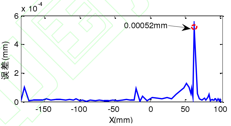
Taking the RTCP operation period 5ms, radius of curvature and vector velocity into the formula, the error caused by prospective control of impeller sand mold is obtained as shown in Figure 7, and the maximum error is 0.00052mm. Compared with figure 5, the maximum error caused by look ahead control occurs at the minimum radius of curvature.
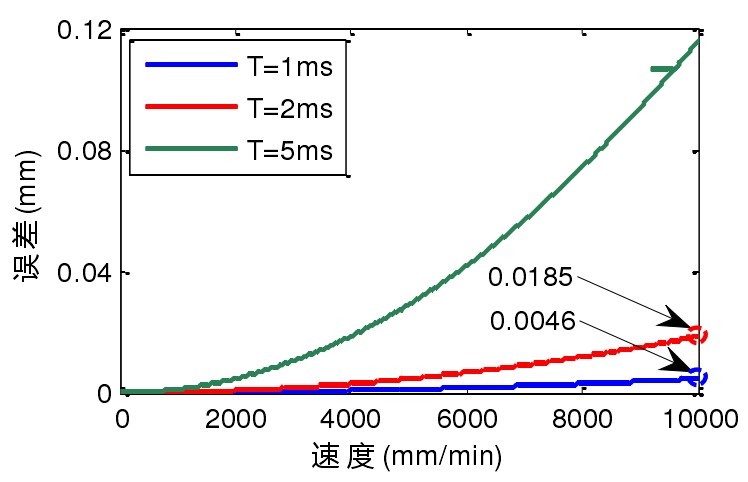
When the RTCP operation cycle is 1ms, 2ms, 5ms, and the curvature radius is 1mm profile, the error caused by look ahead control is calculated according to the formula without considering the cutter, as shown in Fig. 8. It can be seen that when the “sharp corner” profile curvature radius is small and the feed rate is very high, it is necessary to further shorten the RTCP operation cycle to reduce the profile error caused by look ahead control.
Through the prospective control of X, y, Z three linear axes in five axis linkage, the speed control of five axis linkage is realized. In contrast, the forward-looking control mode proposed in this paper can control any one of the five coordinate axes and control the overall speed of five axis linkage machining, which greatly reduces the calculation amount of look ahead control online calculation, and is more flexible, convenient and more practical.