
1. Introduction
The foundry industry is facing unprecedented challenges and opportunities in the era of global market competition. China, as the world’s largest casting producer, contributes approximately 45% of the global casting output annually. However, the industry is characterized by weak independent innovation capability, outdated process equipment, low energy efficiency, and high pollution emissions. The traditional casting industry urgently needs to achieve green, healthy, and sustainable development through advanced manufacturing technologies.
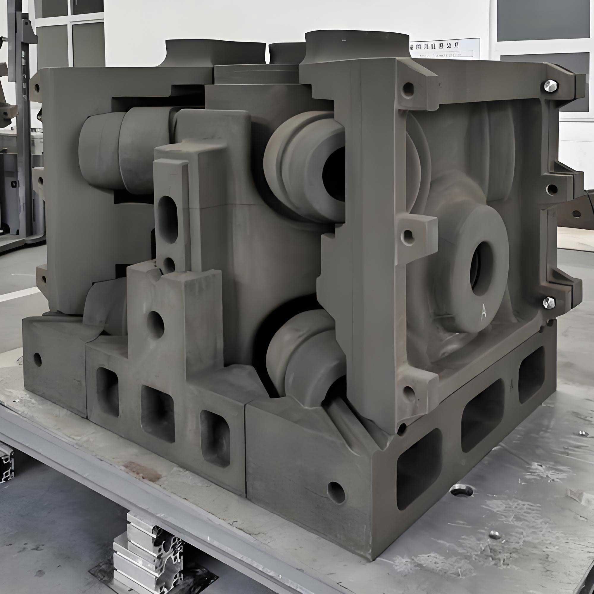
3D printing technology, also known as additive manufacturing, has emerged as a revolutionary approach to address these challenges. Among its various applications, sand mold 3D printing has attracted significant attention in the casting industry. This technology builds sand molds layer by layer directly from CAD models without the need for patterns or core boxes, fundamentally changing the traditional casting process workflow.
The research presented in this thesis focuses on exploring the casting process design method based on ‘3d printing sand casting’ technology. Through systematic analysis of the unique advantages of sand mold 3D printing, this work establishes design principles for casting processes, including gating system design, riser design, mold structure design, and parting surface selection. A comprehensive case study on a bronze tripod casting is conducted to demonstrate the application of these design principles, with numerical simulation used to optimize and validate the proposed casting process.
2. Fundamentals of Sand Mold 3D Printing
2.1 Overview of the Technology
Sand mold 3D printing encompasses two primary methods: Three-Dimensional Printing (3DP) and Selective Laser Sintering (SLS). The 3DP method operates by selectively depositing binder onto a powder bed through an array of print heads. The typical process begins with a mixed sand and curing agent layer uniformly spread across the build platform. The print head then selectively jets binder onto the sand bed according to the slice data of the digital model, causing the sand particles to bond together where the binder is deposited. This layer-by-layer process continues until the complete sand mold is formed.
The SLS method, in contrast, uses a laser beam to selectively sinter resin-coated sand particles. While SLS offers excellent precision, its scanning mechanism limits the maximum build size and production efficiency. For large and medium-sized castings, the 3DP method demonstrates significant competitive advantages. These advantages are summarized in Table 1.
Table 1: Comparison of Sand Mold Manufacturing Methods
| Parameter | Traditional Sand Casting | SLS Sand Mold | 3DP Sand Mold |
|———–|————————|—————|—————-|
| Pattern requirement | Required | None | None |
| Maximum build size | Limited by flask | Limited (usually small) | Large (up to 4000×2000×1000 mm) |
| Production speed | Moderate | Slow | Fast |
| Binder type | Various | Resin-coated sand | Furan/phenolic/silicate |
| Energy consumption | Low | High (laser) | Low |
| Material waste | Moderate | Low | Very low |
| Surface quality | Good | Excellent | Good |
| Green sustainability | Moderate | Good | Excellent |
2.2 Technical Advantages in Casting Process Design
The ‘3d printing sand casting’ technology eliminates many constraints inherent in traditional pattern-based mold making. In traditional sand casting, the pattern must be withdrawn from the mold, requiring draft angles on all vertical surfaces. Core boxes must be designed and manufactured separately. Complex castings often require multiple parting surfaces and multiple cores that need individual assembly.
Sand mold 3D printing removes these constraints entirely. The mold design is no longer limited by pattern withdrawal requirements. Draft angles become unnecessary for many features. Core and mold can be integrated into a single printed structure. Complex internal channels and undercuts can be printed directly without additional core assemblies. Furthermore, the parting surface no longer needs to be planar – it can follow non-planar contours to optimize the casting process.
3. Design Principles for ‘3D Printing Sand Casting’ Process
3.1 Gating System Design
3.1.1 Sprue Design
In traditional horizontal parting sand molds, the sprue must be straight with a draft angle to allow pattern withdrawal. However, ‘3d printing sand casting’ allows the sprue to be curved or serpentine, even with horizontal parting. This design freedom provides significant advantages in controlling metal flow.
The curved sprue design creates a throttling effect through wall friction, effectively reducing the flow velocity of molten metal. Numerical simulations comparing straight and curved sprues demonstrate this benefit clearly. For a straight sprue, metal reaches the sprue well at approximately 1.6 m/s, while the curved sprue reduces the velocity to 1.2 m/s. This velocity reduction minimizes turbulent flow, reduces splashing at the sprue well, and decreases the likelihood of sand erosion and gas entrapment.
The pressure at the bottom of the sprue well also shows significant differences between the two designs. The curved sprue produces a peak pressure of approximately 1.03 MPa at the well bottom, whereas the straight sprue generates a higher impact pressure near 1.14 MPa. The lower pressure from the curved design reduces the risk of mold erosion and the formation of sand inclusion defects.
3.1.2 Runner and Ingate Design
Traditional casting process design positions runners and ingates on the parting surface due to pattern withdrawal constraints. This restriction frequently forces compromises in the gating system layout. With ‘3d printing sand casting’, runners and ingates can be positioned at any location on the mold cavity surface, permitting optimal placement based on filling and solidification requirements.
For tall castings, mid-gating becomes feasible without complicating mold construction. The mid-gate injection system combines advantages of both top-gating (short filling path, high initial temperature) and bottom-gating (smooth filling, good slag separation). This flexibility extends to multiple-step gating systems where, traditionally, each gate level working with a distinct parting line may be needed to avoid three-box molding complications. 3D printing enables a complex multi-step gating design within a simple two-part mold assembly.
Table 2: Traditional and 3D-Printed Gating System Design Advantages
| Design Feature | Traditional Method | 3D Printing Sand Casting |
|—————-|——————-|————————–|
| Sprue shape | Straight with draft | Curved/serpentine allowed |
| Runner position | On parting surface | Any position on mold |
| Ingate position | Restricted by parting | Optimized for solidification |
| Multi-step gating | Requires multi-part molding | Integrates in two-part mold |
| Flow control | Limited | Enhanced flow regulation |
3.2 Riser Design
The spherical riser represents the ideal shape for casting solidification because it provides the smallest surface area-to-volume ratio among all geometric forms, thereby minimizing heat loss and maximizing feeding efficiency. Traditional casting processes rarely utilize spherical risers, however, because they cannot be easily withdrawn from the sand mold. Instead, cylindrical or cylindrical-with-spherical-top risers are commonly employed.

For equal volume V, the surface areas of different riser geometries can be calculated as shown:
For a sphere:
$$R_s = \left(\frac{3V}{4\pi}\right)^{1/3}$$
For a hemispherical-top cylinder:
$$R_h = \left(\frac{16V}{9\pi}\right)^{1/3}$$
Table 3: Surface Area Comparison of Equal Volume Risers
| Riser Type | Radius Relationship | Surface Area |
|————|——————–|—————|
| Sphere | $R_s=(3V/4\pi)^{1/3}$ | $(36\pi)^{1/3}V^{2/3}$ |
| Hemispherical-top cylinder | $R_h=(16V/9\pi)^{1/3}$ | $2V/R_h+5\pi R_h^2/3$ |
| Cylinder | $R_c=(V/\pi H)^{1/2}$ | $2V/R_c+2\pi R_c^2$ |
The mathematical comparison demonstrates that for any given volume, the spherical riser always possesses the smallest surface area. This property leads to slower cooling, extended liquid state duration, and more effective feeding of the casting during solidification. With ‘3d printing sand casting’, spherical risers can be easily incorporated into the mold design without the need for pattern withdrawal considerations.
3.3 Mold Structure Design
3.3.1 Core and Integral Mold Design
Traditional casting processes require separate core boxes for producing cores that form the internal features of castings. These cores must be manufactured, cured, and then installed in the mold with precise positioning. This process introduces the risk of core shift and assembly errors. In ‘3d printing sand casting’, cores can be printed as integral parts of the mold. The core and mold form a unified structure, eliminating the necessity for separate core production, core installation, and associated positioning errors. This integration simplifies the production workflow while improving dimensional accuracy.
For complex internal geometries requiring multiple assembled cores in traditional processing, ‘3d printing sand casting’ allows a single overall core structure to be manufactured in one operation, as a single integrated body. Such complex integrated cores would be impossible to achieve with traditional core box approaches.
3.3.2 Mold Wall Thickness and Structural Design
Traditional sand molds are typically confined within a standardized flask, and the mold wall thickness is determined largely by the flask shape and dimensions. This approach results in thick, non-functional sand layers that are merely present because the flask boundary is far from the cavity. In contrast, ‘3d printing sand casting’ allows the mold wall thickness to be precisely designed based on mechanical performance requirements, saving casting materials and improving mold properties such as heat dissipation and gas permeability.
The design of functional sand wall thickness involves mechanical analysis of the mold under the forces of molten metal and sand. For a horizontal wall surface:
$$T \geq \frac{5\rho g h L^3}{256 E k}$$
And for a vertical wall surface:
$$T \geq \left( \frac{25.5056 \rho g H^4}{256 E k T^3} \right)^{1/3}$$
where T is the functional sand layer thickness, L is the span of the horizontal wall, H is the wall height, h is the vertical distance from the sand wall top to the highest metal surface, ρ is the sand density, E is the elastic modulus, σ_b is the tensile strength, and g is gravitational acceleration.
The casting structure can also be designed with intentional heat transfer features. For example, in a flat plate casting with a central hot spot, the mold wall thickness at that location can be locally reduced. This reduction accelerates heat extraction, promoting simultaneous solidification of the entire casting and reducing warping and shrinkage defects.
3.4 Parting Surface Design
Several principles guide the parting surface design in ‘3d printing sand casting’:
(1) Minimize the number of mold blocks. Each parting introduces potential assembly errors. Therefore, the mold should be divided into as few blocks as possible while still allowing for application of mold coating, sand removal from large cavities, and safe handling.
(2) Complex thin-wall features on the inner mold surface should be grouped within the same mold block. This prevents assembly misalignment from affecting intricate features.
(3) The size and structure of each mold block must be appropriate for manual handling and assembly. Large blocks should incorporate lifting points or handles where necessary. Assembly alignment features, such as tapered dowels or matching socket structures, should be included for accurate positioning.
(4) For castings with thin walls and extensive flat surfaces, the parting surface can be inclined. This inclination creates an angled casting position that facilitates metal filling. In traditional casting, the mold is often tilted by placing spacers under one side of the flask after molding. With 3D printing, the tilt angle can be built directly into the mold geometry, eliminating the need for handling heavy flasks.
3.5 Positioning of Mold Blocks in the Print Bed
Printing efficiency and part quality are significantly influenced by the placement of mold blocks in the printer sand bed. Several rules govern optimal sand block positioning:
(1) Pack mold blocks tightly. Since the printing process simultaneously manufactures all blocks in a single bed, the packing arrangement should maximize bed utilization.
(2) Orient blocks to minimize bed height. The total print time is primarily determined by the maximum bed filling height. Blocks taller than their width should be oriented horizontally where possible to reduce bed height. The relationship can be expressed as:
$$H_{bed} = \max_{i}(H_{block,i})$$
where H_bed is the minimum achievable sand bed height, and H_block is the height of each block in the chosen orientation.
(3) Orient surfaces with curves horizontally. Since layer-based manufacturing creates a staircase effect on inclined surfaces, curved surfaces should be oriented so that the curve lies flat in the horizontal plane. For a block with a cylindrical feature, placing the cylinder axis horizontally ensures the curved surface is built vertically, minimizing visible layer lines. This produces superior surface finish.
(4) Orient surfaces with slopes vertically. For a block containing a flat inclined surface, placing that surface vertically in the sand bed eliminates any staircase steps along the incline, producing a smooth finished surface.
4. Case Study: Bronze Tripod Casting
4.1 Casting Description
The bronze tripod chosen for this case study, weighing 33 kg, has a maximum external diameter of 309 mm, an overall height of 410 mm, and wall thicknesses varying between 5 mm and 34 mm. The casting comprises three legs with hollow internal structures, two ring-shaped handles that are unsymmetrical, and complex artistic surface patterns.
The material is C90300 tin bronze per ASTM B584. This alloy provides good corrosion resistance, satisfactory casting fluidity, excellent weldability and machinability, and is suitable for artistic coloring processes. According to the standard, its composition is:
Table 4: C90300 Bronze Composition
| Element | Cu | Sn | Zn | Ni | Pb | Fe | Sb | P |
|———|—-|—-|—-|—-|—-|—-|—-|—-|
| wt% | Balance | 7.5–9.0 | 3.0–5.0 | 1.0 | 0.30 | 0.20 | 0.20 | 0.05 |
Using the Scheil model within ProCAST software, the thermal-physical parameters of this alloy were computed as:
Table 5: C90300 Bronze Physical Parameters
| Parameter | Value | Unit |
|———–|——-|——|
| Thermal conductivity | 71.8 | W/(m·K) |
| Density | 8.2×10³ | kg/m³ |
| Liquidus temperature | 1003 | ℃ |
| Solidus temperature | 633 | ℃ |
| Latent heat | 365.9 | kJ/kg |
| Thermal expansion coefficient | 1.2×10⁻⁵ | K⁻¹ |
4.2 Molding Material Selection
The molding materials selected for this application are presented in the following table:
Table 6: Molding Materials
| Material | Specification | Standard |
|———-|—————|———-|
| Silica sand | 70/140 mesh | GB/T 9442-2010 |
| Furan resin binder | Furan resin | JB/T 7526-2008 |
| Curing agent | p-Toluenesulfonic acid | GB/T 21872-2008 |
| Coating | Alcohol-based bauxite coating | Al₂O₃ content ≥91% |
4.3 Process Design
The casting includes thick sections at the handles (34 mm) and legs, alongside thin sections (5–10 mm) forming the body. To achieve complete mold filling of these thin sections, the casting is oriented with the three legs facing downward, positioning the handles at the bottom of the mold. Alternative orientation would be necessary if using top-gating or step-gating where this constraint may not apply.
No machining allowance is required since the cast surface is the final artistic surface. The casting shrinkage allowance is set at 1.2%. Since the mold is formed by 3D printing, no draft angles are necessary, and no patterning taper is needed.
The pouring time for this casting is calculated through the relationship:
$$\tau = S_1 \sqrt{m}$$
where m is the total mass of metal inside the mold, and S₁ is a coefficient determined by average wall thickness. For castings with wall thickness between 8 and 15 mm, S₁ equals 2.2. With the casting mass computed at 33 kg and an anticipated process yield of approximately 60%, the total required filling mass is calculated to be 47 kg, resulting in a pour time of 17 seconds.
After evaluating two proposed gating systems, the initial open-runner mid-gate system and the open-ladder (step) gate system, the latter was ultimately selected. A comparison of the two approaches is shown in Table 7.
Table 7: Gating System Options
| System Type | Open Mid-Gate System | Open Step Gate System |
|————-|———————-|———————–|
| Gating ratio ΣA_sprue:ΣA_runner:ΣA_ingate | 1:1.4:1.7 | 1:1.9:2.7 |
| Sprue diameter | Φ40 mm | Φ40 mm |
| Number of runners | 3 | 4 |
| Number of ingates | 3 | 7 |
| Pouring time | 14 s | 12 s |
| Process yield | 70% | 75% |
The cross-sectional areas of the step gating components were calculated as follows. For the sprue:
$$\sum A_{sprue} = \frac{\pi \times 40^2}{4} = 12.56 \text{ cm}^2$$
For the runners:
$$\sum A_{runner} = 1.9 \times 12.56 = 23.9 \text{ cm}^2 \approx 24 \text{ cm}^2$$
Each of the four runners has an area of:
$$A_{runner} = \frac{24}{4} = 6 \text{ cm}^2$$
The runner dimensions are 30 mm × 20 mm.
For the ingates:
$$\sum A_{ingate} = 2.7 \times 12.56 = 33.9 \text{ cm}^2 \approx 34 \text{ cm}^2$$
To preserve the artistic surface of the casting, seven ingates are employed. Four ingates are positioned at the top of the casting body, each with dimensions 20 mm × 20 mm (area 4 cm²), and three ingates feed the legs, each with dimensions 30 mm × 20 mm (area 6 cm²).
4.4 Mold Design and Assembly
The complete sand mold is designed as a cylindrical structure, optimizing sand material usage while promoting uniform heat dissipation around the casting. The design is divided into separate blocks to facilitate mold coating application and interior cleaning, while minimizing the total number of blocks. The final optimized configuration divides the mold into 5 blocks: one upper block, and four lower blocks with associated cores integrated to reduce assembly error.
The upper and lower blocks are joined using a tapered socket alignment mechanism. Prior research has established that for sand molds, a circular tapered socket provides high assembly strength, with an optimal draft angle selection of approximately 10 degrees. This design ensures precise alignment during assembly and provides stability during handling and pouring. Additionally, locating holes and recesses are incorporated into the block design for lifting equipment.
5. Numerical Simulation and Analysis
5.1 Simulation Setup
The casting process was modeled using ProCAST finite element software. The three-dimensional geometry was created in SolidWorks and then imported into ProCAST for mesh generation. The body of the casting model was simplified by removing delicate surface patterns in areas far from the critical gate and riser regions, retaining only the lower leg patterns to reduce computational requirements while maintaining procedural accuracy.
The mesh was refined to ensure at least 2 to 3 elements through the thinnest wall section. For the open mid-gate system, 164,038 surface elements and 3,732,237 volume elements were used. For the step-gating system, 147,128 surface elements and 3,336,876 volume elements were used.
Simulation parameters are listed below:
Table 8: Simulation Input Parameters
| Parameter | Value |
|———–|——-|
| Gravity (m/s²) | 9.8 |
| Mold-metal interfacial heat coefficient (W/m²·℃) | 500 |
| Mold material | Furan resin-bonded sand |
| Initial mold temperature (℃) | 25 |
| Metal initial temperature (℃) | 1150 |
| Filling method | Gravity casting |
| Maximum time step (s) | 0.1 |
| Simulation stop temperature (℃) | 623.98 |
5.2 Analysis of the Initial Step Gating Design
The Open Step Gate System was evaluated through simulation. The filling process is shown through four stages: 25%, 50%, 75%, and complete filling. The molten metal enters through the pouring cup, flows through the runner system which effectively reduces the flow velocity, and then divides into multiple streams entering the mold cavity through the ingates. This split flow configuration was found to effectively promote the removal of internal cavity air and avoid gas entrapment.
The velocity distribution during filling indicates that the maximum velocity of molten metal inside the cavity remained below 0.5 m/s throughout the filling process, confirming smooth cavity filling without jetting or mold erosion.
The solidification analysis reveals that the casting generally solidifies in a bottom-to-top direction, which is the preferred sequence for progressive feeding. However, the thick handle sections cool more slowly and solidify after adjacent areas have already solidified. In particular, the internal regions of the handles transform into isolated hot spots because the surrounding metal has already solidified and cannot feed them. The simulation results predict significant shrinkage porosity in the handle regions and at the junction between the legs and the casting body.
5.3 Comparative Analysis of Mid-Gate and Step Gate Systems
Table 9: Comparison of Solidification Characteristics
| Parameter | Mid-Gate System | Step Gate System |
|———–|—————–|——————|
| Solid fraction at 60 s | 26.4% | 31.7% |
| Solid fraction at 300 s | 80.7% | 86.4% |
| Total solidification time | 1140 s | 890 s |
| Solidification direction | Top-down | Bottom-up |
| Gas entrapment risk | Present | None |
| Process yield | 70% | 75% |
The step gate system proves superior in all relevant criteria. The solidification time is 250 seconds shorter, the process yield increases, and undesirable top-down solidification with gas entrapment risk is eliminated.
5.4 Riser Design Improvements
To address the remaining defects in the handle areas of the step gate design, four different modification schemes were analyzed:
(1) Enlarging the gas vent as a cooling opening
(2) Adding open risers
(3) Adding hemispherical-top blind risers (conventional design)
(4) Adding spherical blind risers with a neck and top exhaust
Each of these schemes was simulated under identical conditions. The key findings are shown below:
Table 10: Riser Design Alternatives Assessment
| Scheme | Filling Complete | Solidification Direction | Defects | Remarks |
|——–|——————|————————–|———|———|
| (1) Open vent | Yes | Bottom-up | Severe shrinkage porosity at handles | Inadequate feeding |
| (2) Open riser | Yes | Bottom-up | Moderate defects at handle-riser junction | Some improvement |
| (3) Blind hemispherical riser | Yes | Bottom-up | Minor defects at leg-body junction | Effective feeding |
| (4) Spherical blind riser | Yes | Bottom-up | Minimal defects, not affecting load-bearing areas | Optimal solution |
A cross-sectional examination of the predicted defects showed that in Scheme 3, the remaining defects were located at the junction of the legs and the body, which are critical load-bearing positions. In Scheme 4, only minor defects were found on the body surface, not influencing structural strength. Figure 4.22 shows the solidification end times for both the hemispherical blind riser design and the spherical riser design. The spherical blind riser demonstrated a higher freezing time, confirming its superior feeding capability because of the smaller surface-area-to-volume ratio, which keeps its internal metal molten for a longer duration.
Additionally, for the spherical riser design with a neck and top exhaust: The process yield for the hemispherical riser scheme was 72%, whereas the spherical riser resulted in a yield equal to 75%. Furthermore, the neck design of the spherical riser is detaching more readily from the casting, which simplifies the finishing work. Based on these results, the spherical blind riser with a neck is selected as the preferred configuration.
5.5 Final Optimized Process Parameters
The optimized casting process for the bronze tripod is summarized in Table 11:
Table 11: Optimized Casting Process Parameters
| Parameter | Value |
|———–|——-|
| Casting net weight (kg) | 33 |
| Casting total weight including gating (kg) | 44 |
| Total poured metal weight (kg) | 50 |
| Process yield (%) | 75 |
| Gating system type | Open (step or ladder) |
| Cross-sectional area ratio (sprue:runner:ingate) | 1:1.9:2.7 |
| Sprue diameter (mm) | Φ40 |
| Riser type | Spherical blind with neck |
| Molding material | Furan resin, p-toluenesulfonic acid, silica sand |
| Mold manufacturing method | 3D printing sand casting |
| Mold assembly | 5-block assembly with tapered alignment |
| Coating material | Alcohol-based bauxite coating |
| Melting furnace | 0.5 t medium-frequency induction furnace |
| Furnace tapping temperature (℃) | 1200 |
| Pouring temperature (℃) | 1150 |
| Pouring time (s) | 12 |
| Mold cooling time (s) | 1050 |
6. Conclusion
This thesis comprehensively investigates the casting design method based on ‘3d printing sand casting’ technology. The main conclusions are as follows:
(1) Design principles for ‘3d printing sand casting’ processes: The unique characteristics of 3D-printed sand molds permit innovations in gating system geometry (including curved sprues for flow control and off-parting runners/ingates), allow the use of perfectly spherical risers for optimal thermal efficiency without demolding constraints, and enable the full integration of cores into the mold structure.
(2) Mold structure design: The mold walls should be dimensioned according to mechanical strength requirements through engineering calculation instead of being dictated by flask dimensions. Large functional cavities can be placed inside the mold to enhance cooling and reduce material consumption. The parting surface configuration can be non-planar or spatially inclined, significantly expanding the practical design envelope.
(3) Printing bed positioning rules: The packing of the sand mold blocks within the print bed significantly affects printing efficiency. Blocks should be arranged tightly, oriented to reduce total bed height, and positioned so that any curved surfaces are horizontal and any inclined flat surfaces are vertical, thereby reducing staircase and layer artifacts.
(4) Bronze tripod case study: An integrated one-piece bronze tripod casting has been developed and optimized, where the traditional approach of casting six separate components followed by welding is replaced by a single-step complete mold print resulting in a fully formed casting. An open step (ladder) gating system with spherical blind risers provides the highest quality cast product and process yield: 75%. The final process parameters include a pouring temperature of 1150 ℃, a pouring time of 12 seconds, and a melt furnace tapping temperature of 1200 ℃.
The integrated mold design, multiple cavity feeding, placement of ingates without parting constraints, free choice of parting line, intentional functional wall thicknesses, and unrestricted spherical riser geometry all constitute major advantages, demonstrating the power of ‘3d printing sand casting’ for complex, high-quality castings.