
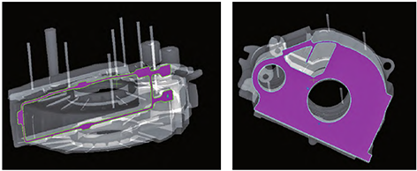
The variable speed box material is EN-GJS -400 -18 -LT (EN1563), the part weight is 128.8 kg, the casting weight is 162 kg, the box structure is 961 mm× 596 mm× 252 mm, Figure 1 is a three-dimensional drawing of the casting. The identified locations in the casting drawings (see Figure 2) are radiographic flaw detection level 2 and the rest are radiographic flaw detection level 3. During mass production, castings must be inspected for ultrasonic flaw detection, and the location and requirements of ultrasonic flaw detection are consistent with those of radiographic flaw detection.
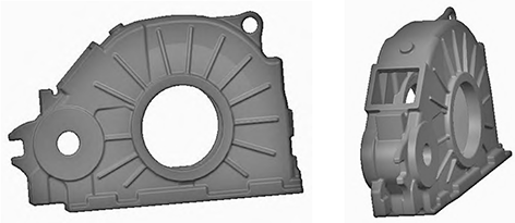
Figure 1 Three-dimensional structural diagram of gearbox body castings
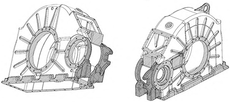
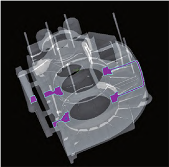
Figure 2 Illustration of the internal mass of a casting
1 Casting process scenario and Procast process simulation
1.1 Casting process scheme
According to the product structure and quality requirements, the intermediate parting of the gearbox body is adopted in the process design, as shown in Figure 3, and the sand box tooling uses 1 140 mm × 1 020 mm universal sand box. The inner cavity of the gearbox uses the sand core structure, and the external lifting structure designs the sand core, a total of 4 sand cores, as shown in Figure 4, the 1# and 2# sand cores of the gearbox inner cavity must first fall into the 3# sand core, and fall into the lower type with the 3# sand core, and the 4# sand core A 20 mm make-up zone is reserved on the back and pushed from the outside in to the fixed position. The gating system adopts a top pouring closed pouring system, the blocking section is on the inner gate, and the molten metal is easy to fill the pouring system after the pouring starts.Strong slag blocking ability, less molten metal consumption, and easy to clean. The inner gate is dispersed on the flange surface, which is convenient for casting cleaning, according to the determination of wall thickness and pouring time, the size of the gating system is calculated according to the choke section design method, where F straight: F horizontal: F inside = 2.04: 1.64∶1, the pouring temperature is 1 350 °C~1 370 °C, and the pouring time is 25 s.
1.2 Procast process simulation
To verify the rationality of the gearbox body casting process design, a process simulation was performed by Procast, as shown in Figure 5. The simulation results showed crater defects. The shrinkage holes are all at the thermal joints of the structure, which is the main original Due to the sudden change in the wall thickness of the casting structure, the isolated hot joint cannot be replenished. In order to prevent shrinkage defects during process testing, a cold iron is placed at the simulated defect location for rapid cooling and insulation risers at the hot joints Perform liquid replenishment.
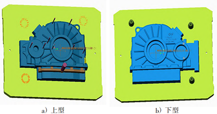
Figure 3 External mold structure of gearbox
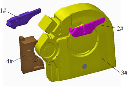
Figure 4 Sand core structure of the gearbox body
2 Process test verification and results
2.1 First test verification
According to the process simulation results, the cold iron and insulation riser were placed in the corresponding positions of the gearbox body, see Figure 6.The pouring temperature was 1 370 °C, the pouring time was 23 s, the outer mold coating was alcohol-based paint flow coating, and the cold iron part was baked by a gas blowtorch.
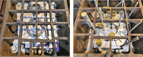
Figure 6 Gearbox body riser and cold iron layout drawing
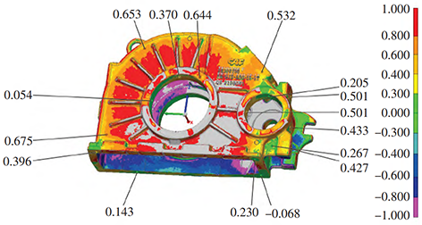
Figure 7 Results of a 3D scan of a casting
The results of the first test showed that:
1) The cleaned castings are scanned in 3D to conform to the design 3D (see Figure 7 3D scan comparison chart);
2) X-ray flaw detection results showed that no defects were found in the shrinkage defect location during the process simulation, but a 4-stage shrinkage defect was found at the contact position between the hook and the gearbox body (see the position of piece 29 in Figure 8), outside
3 levels of shrinkage were found at the connection between the thick part and the gearbox body (see the position of piece 13 in Figure 8);
3) After shot blasting, the gearbox body casting is found to have skin porosity defects at the upper plane (see Figure 9), which affects the appearance quality of the casting;
4) The low temperature impact values of the attached casting samples are 8 J, 10 J, 10 J, and the low temperature impact does not comply with EN 1563.
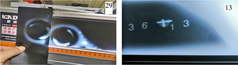
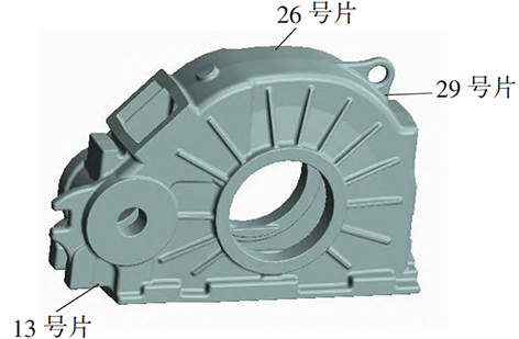
Figure 8 Radiographic flaw detection picture
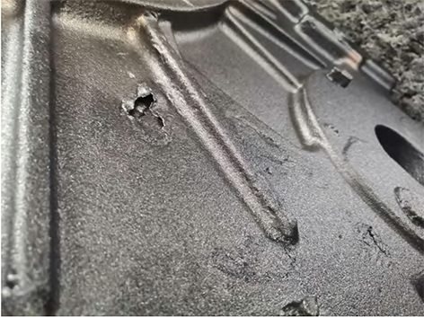
Figure 9 Surface stomatal defects
Analysis of the first test defects showed that:
1) In radiographic testing, the defect positions of No. 13 and No. 29 pieces are connected to the box, which belong to independent hot joints, and the analysis believes that the wall thickness of this connection part is thicker than that of other non-connected parts, and it is necessary to increase cold iron to accelerate
These two cooling rates reduce or eliminate these two shrinkage defects.
2) The surface pores defect after shot blasting is located opposite the pouring system, away from the pouring system, the analysis believes that the temperature decreases when molten iron flows to the place, resulting in the gas generated by the sand core can not be discharged in time to produce surface pores, should increase the pouring temperature or accelerate the flow of molten iron to the place, the process measure is to increase the pouring temperature, and raise the side of the pouring system to accelerate the flow of molten iron to the opposite side of the pouring system.
3) According to the analysis of the problem of low-temperature impact unqualified attached casting samples, it is believed that the mass fraction containing Si is now 2.2%~2.5%, and a certain amount of Si can promote graphite and prevent the generation of cementite, but Si will increase the brittleness transition temperature of the material and reduce the toughness, and the measure is to reduce the mass fraction of Si to 2.0%~2.2%.
2.2 Second test verification
2.2.1 Second test process improvement
According to the results of the first test analysis, the measures were taken: 1) add rivets and round bars as cold iron at the position of No. 13 and No. 29 to reduce the shrinkage defects in these two places (see Figure 10); 2) Increase the pouring temperature to 1 400 °C, and raise the side of the gating system by 60 mm to reduce the surface porous defect; 3) Reduce the Si mass fraction to 2.0% ~ 2.2% during melting, and improve the low-temperature toughness of the attached casting sample.
2.2.2 Results of the second test
1) X-ray flaw detection results No. 29 and No. 13 are positioned at level 1, which meets the requirements of the drawing (see Table 1);
2) After shot blasting, there is no surface porosity defect on the surface of the casting, and the surface quality of the casting is good;
3) The low temperature impact values of the attached casting samples are 12 J, 14 J, 10 J, and the low temperature impact complies with EN 1563.
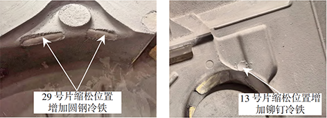
Figure 10 Cold iron layout drawing
3 Conclusion
1) Use reasonable cold iron and riser structure to ensure that the casting is important
The internal quality of the part.
2) Increasing the pouring temperature and raising the pouring system side can increase the flow speed of molten iron and reduce the surface porosity defects far from the side of the pouring system.
3) Reasonable Si content can improve the low-temperature toughness of the attached casting sample.
Table 1 Transmission body flaw detection results
| Piece number | Defect analysis | level | Piece number | Defect analysis | level |
| 1 | A | 1 | 19 | A | 1 |
| 2 | A | 1 | 20 | A | 1 |
| 3 | Cc | 1 | 21 | / | 1 |
| 4 | Cb | 1 | 22 | / | 1 |
| 5 | / | 1 | 23 | A | 1 |
| 6 | Cb | 1 | Cb | 1 | |
| 7 | / | 1 | 25 | / | 1 |
| 8 | / | 1 | 26 | Cc | 1 |
| 9 | / | 1 | 27 | / | 1 |
| 10 | / | 1 | 30 | / | 1 |
| 11 | / | 1 | 31 | Cc | 1 |
| 12 | / | 1 | 32 | Cc | 1 |
| 13 | Cc | 1 | 33 | / | 1 |
| 14 | / | 1 | 34 | / | 1 |
| 15 | / | 1 | 35 | / | 1 |
| 16 | / | 1 | 36 | / | 1 |
| 17 | A | 1 | 37 | Cc | 1 |
| 18 | A | 1 | 38 | / | 1 |
| B | 1 |