This article focuses on the casting process of the pump body using sand 3D printing technology. It includes the design of the pump body structure and parting method, the design and simulation analysis of the gating system, the practical verification process, and the comprehensive conclusion and 展望. By comparing different gating systems through numerical simulation and applying 3D printing technology to make sand molds, the production efficiency is improved, the development cycle is shortened, and high-quality castings are obtained.
1. Introduction
In the field of casting, the traditional sand casting process has certain limitations in dealing with complex parts. With the development of technology, sand 3D printing technology has brought new opportunities. This technology can quickly produce sand molds with high precision, which is of great significance for improving the quality and efficiency of castings. Taking the pump body as the research object, this study combines numerical simulation and sand 3D printing technology to explore the optimal casting process.
2. Pump Body Structure and Parting Method Design
2.1 Pump Body Structure
The pump body is a shell casting with an asymmetric structure. Its external dimensions are 410 mm × 503 mm × 170.5 mm, and the net weight is 57 kg, belonging to a small casting. The material is HT200.
| Parameter | Value |
|---|---|
| External Dimensions | 410 mm × 503 mm × 170.5 mm |
| Net Weight | 57 kg |
| Material | HT200 |
2.2 Determination of Parting Surface
The selection of the parting surface of the casting has a great influence on the successful assembly of the sand mold and the quality of the casting after pouring. When choosing the parting surface, the following aspects need to be considered:
- Reducing the number of parting surfaces can reduce the error of assembling the sand mold and the difficulty of assembly.
- For parts with complex internal or surface structures and thin walls, try to ensure that these parts are placed on one sand block.
- Considering the handling and assembly problems of the sand mold, design gripping points on the upper and lower molds of the sand mold and ensure sufficient strength.
In sand 3D printing, the parting surface of this casting is selected at the maximum cross-sectional area of the casting. Through 3D software modeling, it is verified that this scheme can achieve successful assembly.
3. Scheme Design and Simulation Analysis
3.1 Gating System Scheme Design
Three gating system schemes are designed for the pump body, namely top pouring, side pouring, and bottom pouring.
| Gating System | Description |
|---|---|
| Top Pouring | The molten metal is poured from the top of the casting. |
| Side Pouring | The molten metal is poured from the side of the casting. |
| Bottom Pouring | The molten metal is poured from the bottom of the casting. |
3.2 Filling Process Simulation Analysis
AnyCasting software is used to conduct casting simulation analysis on the pump body. The casting is divided into 1 million regular cube grids with an average size of 5.6 mm × 5.6 mm × 5.6 mm. The casting process parameters are shown in the following table:
| Casting Method | Material | Sand Mold Material | Pouring Temperature | Pouring Time |
|---|---|---|---|---|
| Sand Mold Casting | HT200 | Furan Resin Sand | 1450°C | 18s |
3.2.1 Top Pouring Scheme Simulation Analysis
The overall solidification sequence of the top pouring gating system is from top to bottom and from outside to inside. Except for the riser and gate, the outer wall of the pump body casting cools first due to its thin thickness, while the inner part of the pump body casting cools last. Through defect parameter analysis, it is found that defects may occur on the outer wall and riser of the casting, and shrinkage porosity may also appear on the outer wall and inside of the casting.
3.2.2 Side Pouring Scheme Simulation Analysis
The overall solidification sequence of the side pouring gating system is also from top to bottom and from outside to inside, but the solidification trend is uneven. Similar to the top pouring scheme, the outer wall of the casting cools first and the inner part cools last. By observing the combination defect prediction diagram and the shrinkage porosity fraction diagram, it is found that shrinkage porosity defects only appear at the riser after solidification, and the defects basically do not affect the quality of the casting itself.
3.2.3 Bottom Pouring Scheme Simulation Analysis
The overall solidification sequence of the bottom pouring gating system is the same as the above two schemes. However, the area near the gating system cools slowly. Defects will occur at the junction of the riser and the casting near the casting system, and shrinkage porosity will appear on the middle hole wall and plane. The bottom pouring gating system has poor heat dissipation at the bottom runner and slow melt flow velocity, resulting in casting defects.
Based on the analysis results of the simulation pouring schemes, the side pouring gating system is selected because the defects are concentrated at the riser and there are almost no defects in the casting itself. Nine risers are placed on the surface to be machined later, and the height is the same as the gate plane to ensure smooth gas exhaust and feeding.
4. Practical Verification
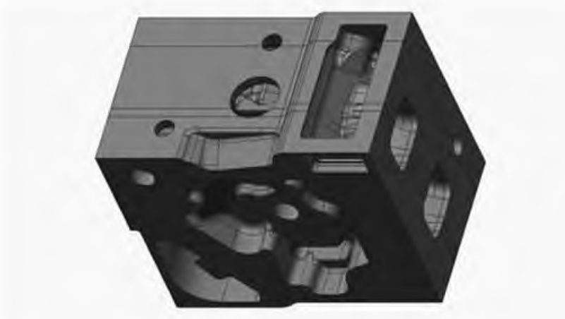
Due to the complex structure of the casting and the difficulty in modeling, the 3D printing method is used to print the sand core. When printing the sand core, the size of the sand core frustum is designed to enhance the fixing strength of the core and facilitate installation. The sand mold is divided into 2 parts. Considering the economic benefits, the wall thickness of the printed sand mold can be optimized under the premise of ensuring strength to reduce the amount of sand used.
The sand mold is printed in the Longyuan AFS-J1600 printer. After testing, the layer thickness of this printing process is determined to be 0.4 mm, and the scan line width is 1.5 mm. After setting the printing parameters, the designed sand mold is output as an STL file and sliced by Magics. Then, the sliced model in cli format output by Magics is imported into the AFS-J1600 printer for printing.
After printing, the unbonded and cured dry sand in the sand mold is cleaned with a vacuum cleaner and supplemented by an air blower. Before pouring, zircon powder is sprayed on the pouring surface of the sand mold to improve the surface quality of the casting and reduce the gas generation amount. The pouring raw material is HT200, the pouring temperature is 1450 °C, and the pouring time is 18 s.
After the casting cools, the outer sand mold is knocked off to obtain a casting without obvious defects. After removing the riser and gating system, the casting is inspected and the quality is qualified, with no obvious shrinkage porosity on the surface and good surface quality.
5. Conclusion and Outlook
In this study, through the numerical simulation analysis of the side pouring, top pouring, and bottom pouring gating schemes of the pump body using AnyCasting software, the side pouring scheme is determined to be the optimal pouring scheme, which shortens the mold trial cycle. The use of 3D printing technology to make sand molds can greatly shorten the sand mold production time. The combination of numerical simulation technology and sand 3D printing technology can extremely shorten the development and trial production cycle of new casting products and improve production efficiency.
In the future, further research can be carried out in the following aspects:
- Optimize the design of the gating system and sand mold structure to further improve the quality of the casting.
- Explore the application of more advanced 3D printing materials and technologies to improve the performance of the sand mold.
- Expand the research objects to other types of castings to verify the universality of this technology.
In general, the combination of sand 3D printing technology and numerical simulation has broad application prospects in the field of casting and will play an important role in promoting the development of the casting industry.