The volute of the pump is a key part cast in a certain type of product and is the main part to improve the performance of the pump. The volute shell of the pump is subject to more impact and corrosion of seawater in the working environment, so the casting requires better internal quality and comprehensive mechanical properties. Its performance and quality play an important role in the operation of the pump.
The casting has thin wall thickness, many curved flow channels, complex structure, dispersed hot joints, difficult casting process, and difficult to control the casting forming process, which brings great challenges to the casting process design.
1 Overview of castings
1.1 Casting external dimensions and performance requirements
The volute wall thickness of the pump is 8mm, and the uninjected wall thickness is ±1mm, which belongs to thin-walled parts. The inner cavity forming is very complex, there is a gradient flow channel, there is a partition on the side of the inner cavity to divide the inner cavity into two parts, at the same time there are two upper and lower flanges in the inner cavity, the flange end face is processed, the rest of the inner cavity is not machined, the casting tolerance size CT10 grade is not injected, and the casting contour size
320mm×323mm×408mm, as shown in Figure 1, the mechanical property requirements of castings are shown in Table 1 and Table 2.
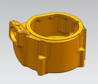
Fig.1 Casting shape
Tab.1 Chemical composition requirements of the casting
| 元素 | Al | Fe | Ni | Mn | Cu |
| 含量(%) | 8.5~10.5 | 4.0~5.5 | 4.0~6.0 | ≤3.0 | 其 余 |
Tab.2 Mechanical properties index of the casting
| 抗拉强度 (MPa) | 屈服强度 (MPa) | 断后延伸率 (%) |
| ≥650 | ≥280 | ≥7 |
1.2 Casting performance of the material
The casting material is ZCuAl10Fe4Ni4, and the casting performance characteristics: the crystallization temperature range is small, it belongs to layered solidification, and the volume shrinks
Large, easy to form concentrated shrinkage holes, at the same time the alloy contains more aluminum, easy to oxidize to form Al2O3 slag inclusion, and it is easy to form secondary oxidation slag during the pouring process.
1.3 Process analysis of casting structure
The casting structure is complex, there are many flow channels and a gradual trend, the hot joint parts are many and complex, and there are hydraulic test requirements, so the quality requirements for castings are high.
1.4 Technical requirements for castings
The casting shall not have casting defects such as porosity, looseness, cracks and slag inclusion; Shot peening required; Non-machined surface roughness Ra25; There shall be no mutation in the overflow part of the inner cavity, and the relative position size of the hole shall be accurate; Uninjected wall thickness± 1mm; Hydrostatic test on the inner cavity after casting processing: 0.5MPa holding pressure for 15min without leakage.
2 Casting process
In order to obtain castings with good performance, dense organization and quality that meet customer requirements, high requirements are put forward for casting process design. Casting process flow: process design→ 3D printing mold → modeling, core making→ melting, pouring→ unpacking, cleaning → cutting riser→ casting shot blasting treatment→ casting scribing→ casting grinding→ machining → hydraulic test.
2.1 Pouring position
The overall casting process is based on gravity casting combined with 3D printing technology. According to the structural characteristics of the casting, alloy material and other elements determine the pouring position, and for the casting, determine the pouring position as the foot plate facing down.
2.2 Main structure of casting
In order to ensure that the wall thickness of the casting is uniform and the quality of the casting meets the technical requirements of customers, the mold and intermediate mud core will be 3D printed.
The gating system is also 3D printed and shaped with dowel pins positioning between the moulds.
2.3 Determine a reasonable parting surface
According to the structural characteristics and quality requirements of the casting, determine the casting flow channel and foot plate facing down, four box shape, along the bottom surface of the casting foot plate, the top surface of the foot plate and the center of the water inlet flange. The specific classification is shown in Figure 2.
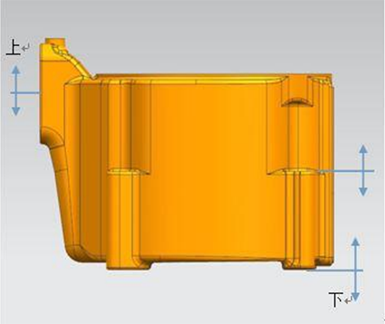
Fig.2 Classification surface of the casting
2.4 Gating system
The design of the gating system should conform to the principle of sequential solidification of castings and the shrinkage method to ensure the smooth flow of molten metal, avoid turbulence, prevent gas involvement, and form oxidation slag. According to the casting performance of the alloy, the casting system is determined to be a bottom injection pouring system, and the molten metal flows from the slag retaining gate cup into a straight runner with a diameter of φ25mm, and enters the inner sprue of 4-φ24mm through a cross channel with a cross section of 35/40×40 (see Figure 3 for the pouring system), which effectively disperses the heat of the molten metal, and at the same time makes the copper liquid flow smoothly into the cavity to avoid casting production
Raw cold partition to ensure the acquisition of high-quality castings.
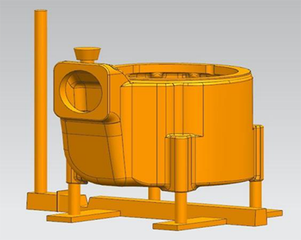
2.5 Riser and its chilled sand design
Setting risers is a commonly used casting process measure, mainly used to prevent shrinkage, shrinkage and other casting defects. Take advantage of risers and agitations
Cold sand to achieve the purpose of controlling the solidification sequence of copper liquid, the riser should be located near the top or side of the hot section of the casting, consider the casting structure, according to the modulus method and the riser filling distance, determine the number and size of the riser, to determine the solidification shrinkage of the casting, the riser can be enough to compensate the shrinkage of the casting alloy liquid [3]. The number and size of risers are as follows: top
The part adopts a circle riser of φ245/φ330×110. Chilled sand design. The four support feet are fully wrapped with chilled sand, and the chilled sand is scooped on site and dried for later use.
2.6 Smelting and pouring
Before pouring, the mold and the intermediate mud core should be baked to ensure that the mold is dry, the drying time is not less than 1.5h, and the temperature is not low
at 110°C. The medium frequency induction electric furnace is used for melting, and the charge is removed from oil, rust spots and other debris, while ensuring that the charge is dry. Reasonable distribution when loading, often pry the charge during the melting process to prevent
Charge stop material shed. When the melting temperature rises to the appropriate temperature for the melting of each metal, the temperature rise is stopped and the heat preservation state is entered. After keeping warm for a period of time, subcontract dumping is carried out, and then pre-furnace testing is done. Degassing treatment is carried out after qualifying. The control temperature is poured in the range of 1150°C-1190°C.
3 Test results
When the casting cools, after unpacking, falling sand, removing the riser, after grinding for testing and chemical composition, mechanical property analysis, after testing, casting chemical composition, mechanical properties, internal and external quality and hydraulic test fully meet customer requirements, casting body see Figure 4, casting profile see Figure 5.
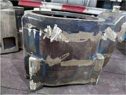
Fig.4 Casting entity
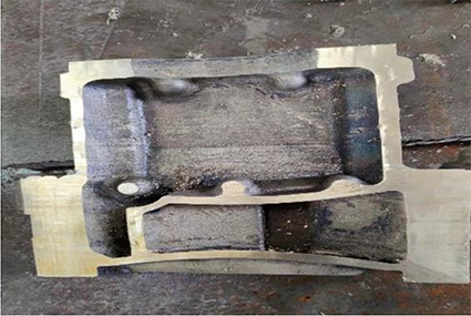
Fig.5 Casting section
4 Concluding remarks
The casting structure is complex, the wall thickness is thin, and there are many hot joints, so the production is difficult, but after the preliminary technical preparation and scheme design, through the combination of actual field experience and on-site control, the optimal casting scheme is used to successfully cast the casting. The chemical composition, mechanical properties, appearance dimensions and water pressure requirements of the castings meet customer requirements, broaden the company’s product structure, and enhance the company’s reputation among users. The casting process has good production indicators and provides valuable experience for the production of similar products.
