
In modern manufacturing, the demand for complex and thin-walled sand casting parts, such as impellers, irregular hulls, and intricate shells, has been increasing. Traditional casting methods often rely on wooden or metal patterns, which are time-consuming, costly, and environmentally taxing. Digital patternless casting technology, which involves machining sand molds directly without physical patterns, offers significant advantages including reduced pollution, shorter production cycles, and lower costs. However, the fabrication of intricate sand molds for these sand casting parts requires advanced five-axis linkage machining to achieve high precision and efficiency. This study focuses on the control technology for five-axis linkage high-speed forming of digital sand casting molds, addressing key challenges in kinematics modeling and speed control.
The core of five-axis machining lies in the Rotation Tool Center Point (RTCP) function, which ensures the tool tip remains on the programmed trajectory even when the tool orientation changes. For sand casting parts with complex geometries, such as those involving undercuts or deep cavities, RTCP is essential to maintain accuracy. This research derives the kinematic model for a B-C double swing head five-axis linkage system, analyzes speed fluctuation mechanisms, and proposes a single-axis look-ahead control strategy to enable high-speed forming of sand molds. The goal is to enhance the efficiency of producing sand casting parts while ensuring stability and quality.
Five-axis machines typically consist of three linear axes (X, Y, Z) and two rotary axes. For sand mold machining, a B-C double swing head structure is often preferred due to its suitability for large-scale sand casting parts. The RTCP function compensates for tool center point deviations caused by rotary axis movements, allowing programmers to focus on the tool path without manually adjusting for tool orientation. The kinematic model for this system is based on coordinate transformations between the workpiece coordinate system, tool coordinate system, and rotary coordinate system.
Let us define the workpiece coordinate system as $O_MX_MY_MZ_M$, with origin $O_M$ at a feature point of the sand casting part. The tool coordinate system is $O_TX_TY_TZ_T$, with origin $O_T$ at the tool tip when the tool axis is parallel to the Z-axis. The rotary coordinate system is $O_RX_RY_RZ_R$, with origin $O_R$ at the intersection of the B and C axes. The tool length is denoted as $L$. The position of the tool tip in the workpiece coordinate system is represented by vector $\mathbf{P}_M = [P_{MX}, P_{MY}, P_{MZ}]^T$. After rotations around the B and C axes, the transformation matrices are:
$$
\mathbf{R}_B = \begin{bmatrix}
\cos B & 0 & \sin B \\
0 & 1 & 0 \\
-\sin B & 0 & \cos B
\end{bmatrix}, \quad
\mathbf{R}_C = \begin{bmatrix}
\cos C & -\sin C & 0 \\
\sin C & \cos C & 0 \\
0 & 0 & 1
\end{bmatrix}.
$$
The tool tip position change due to rotation is given by:
$$
\Delta \mathbf{P} = \mathbf{R}_B \cdot \mathbf{R}_C \cdot \mathbf{T}_L + \mathbf{M}_T,
$$
where $\mathbf{T}_L = [0, 0, -L]^T$ and $\mathbf{M}_T = [0, 0, L]^T$. To maintain the tool tip position, the linear axis coordinates after RTCP compensation are:
$$
\mathbf{P} = \mathbf{P}_M – \mathbf{R}_B \cdot \mathbf{R}_C \cdot \mathbf{T}_L – \mathbf{M}_T.
$$
Expanding this, the inverse kinematics solution for the B-C structure is:
$$
\begin{aligned}
P_X &= P_{MX} + L \sin B \cos C, \\
P_Y &= P_{MY} + L \sin B \sin C, \\
P_Z &= P_{MZ} + L \cos B – L.
\end{aligned}
$$
The forward kinematics, which computes the tool tip position from motor positions, is:
$$
\begin{aligned}
P_{MX} &= P_X – L \sin B \cos C, \\
P_{MY} &= P_Y – L \sin B \sin C, \\
P_{MZ} &= P_Z – L \cos B + L.
\end{aligned}
$$
These equations form the basis for RTCP implementation in five-axis machining of sand casting parts. By cyclically calling the forward and inverse kinematics in the control system, real-time compensation is achieved, ensuring precise tool positioning during complex mold machining.
High-speed machining of sand casting parts requires efficient feedrate control to minimize cycle times. However, in five-axis linkage, speed fluctuations can occur due to RTCP compensation, leading to excessive linear axis velocities that may cause vibration, tool wear, or damage to the brittle sand mold material. The programmed feedrate $F$ is based on the tool tip path, but the actual axis velocities depend on the RTCP-calculated positions. For a segment between two programmed points, the time interval $t$ is:
$$
t = \frac{\sqrt{\mu_X^2 \Delta P_{MX}^2 + \mu_Y^2 \Delta P_{MY}^2 + \mu_Z^2 \Delta P_{MZ}^2 + \mu_B^2 \Delta B^2 + \mu_C^2 \Delta C^2}}{F},
$$
where $\mu_X, \mu_Y, \mu_Z, \mu_B, \mu_C$ are scaling factors converting units to pulses. The actual axis velocities are:
$$
\begin{aligned}
V_X &= \mu_X \frac{\Delta P_X}{t}, \\
V_Y &= \mu_Y \frac{\Delta P_Y}{t}, \\
V_Z &= \mu_Z \frac{\Delta P_Z}{t}, \\
V_B &= \mu_B \frac{\Delta B}{t}, \\
V_C &= \mu_C \frac{\Delta C}{t}.
\end{aligned}
$$
The resultant feedrate $F_{\text{act}}$ often exceeds $F$ due to RTCP adjustments, especially with long tool lengths common in sand mold machining for large sand casting parts. This speed overrun can be analyzed by the ratio:
$$
F_{\text{act}} = F \times \frac{\sqrt{\mu_X^2 \Delta P_X^2 + \mu_Y^2 \Delta P_Y^2 + \mu_Z^2 \Delta P_Z^2 + \mu_B^2 \Delta B^2 + \mu_C^2 \Delta C^2}}{\sqrt{\mu_X^2 \Delta P_{MX}^2 + \mu_Y^2 \Delta P_{MY}^2 + \mu_Z^2 \Delta P_{MZ}^2 + \mu_B^2 \Delta B^2 + \mu_C^2 \Delta C^2}}.
$$
To mitigate this, a look-ahead control strategy is proposed. The key insight is that the velocity ratios between axes are constrained by their position change ratios. For example, the ratio between X and Y velocities is:
$$
\frac{V_X}{V_Y} = \frac{\mu_X \Delta P_X}{\mu_Y \Delta P_Y}.
$$
Thus, by controlling the velocity of one axis, the others can be implicitly regulated. This allows for single-axis look-ahead control to manage the overall five-axis speed. The look-ahead threshold for an axis, say the Z-axis, is calculated based on the limits of all axes. Let $V_{\text{limit}}^{+}$ and $V_{\text{limit}}^{-}$ be the positive and negative velocity limits for each axis. The Z-axis velocity constraint is:
$$
V_{Z}^{\text{threshold}} = \min \left\{
\begin{aligned}
&\left| \frac{\Delta P_Z}{\Delta P_X} V_{X}^{\text{limit}} \right|, \\
&\left| \frac{\Delta P_Z}{\Delta P_Y} V_{Y}^{\text{limit}} \right|, \\
&\left| V_{Z}^{\text{limit}} \right|, \\
&\left| \frac{\Delta P_Z}{\Delta B} V_{B}^{\text{limit}} \right|, \\
&\left| \frac{\Delta P_Z}{\Delta C} V_{C}^{\text{limit}} \right|
\end{aligned}
\right\}.
$$
Similar formulas apply for other axes. By setting the look-ahead threshold for one axis, the control system can pre-plan acceleration and deceleration profiles to prevent speed violations. The number of look-ahead segments $N$ required is given by:
$$
N = \frac{V_{\text{threshold}}}{2 A_{\text{max}} \cdot t_s},
$$
where $A_{\text{max}}$ is the maximum acceleration of the controlled axis and $t_s$ is the servo cycle time. This approach reduces computational load compared to full five-axis look-ahead, making it practical for real-time applications in sand casting parts manufacturing.
To validate the proposed methods, experiments were conducted using an open-control system based on a Programmable Multi-Axes Controller (PMAC). A five-axis digital patternless casting machine was employed, equipped with a B-C double swing head and a high-speed spindle. The sand mold for an impeller, a common sand casting part, was machined to test the RTCP implementation and look-ahead control. Key parameters of the machine are summarized in the table below:
| Axis | Travel Range | Max Speed | Positioning Accuracy |
|---|---|---|---|
| X | 1500 mm | 12000 mm/min | ±0.05 mm/300 mm |
| Y | 2000 mm | 12000 mm/min | ±0.05 mm/300 mm |
| Z | 700 mm | 12000 mm/min | ±0.05 mm/300 mm |
| C | ±360° | 60 rpm | ±20 arcsec |
| B | ±90° | 30 rpm | ±20 arcsec |
The tool length $L$ was measured as 403.70 mm, and a 10 mm diameter hollow end mill was used for machining the sand mold. The RTCP forward and inverse kinematics were programmed into the PMAC with a cycle time of 5 ms. The impeller sand mold was designed with complex blades, requiring five-axis interpolation. The programmed feedrate was set to 500 mm/min initially, and then increased to 2500 mm/min for high-speed tests. The machining process was monitored for position accuracy and speed profiles.
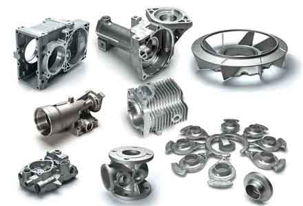
Figure below shows an example of a sand casting part produced using similar five-axis machining techniques, highlighting the intricate geometries achievable with digital mold forming:
During machining, the actual axis positions were recorded and compared with the RTCP inverse kinematics simulations. The error between the actual and simulated positions was analyzed, with results showing maximum deviations of 0.036 mm in the Y-direction and 0.034 mm in the Z-direction at a feedrate of 500 mm/min. When the feedrate was increased to 2500 mm/min without look-ahead control, the errors grew to 0.072 mm and 0.077 mm, respectively, due to higher accelerations. The velocity profiles for the linear axes exceeded the programmed feedrate, with peaks reaching -6440 mm/min for X, -7528 mm/min for Y, and -6119 mm/min for Z, causing noticeable vibration.
To address this, the single-axis look-ahead control was applied using the Z-axis as the controlled axis. Based on the axis limits (2500 mm/min for linear axes and 1000°/min for rotary axes), the Z-axis look-ahead threshold was calculated as 1234.1 mm/min. The look-ahead was configured with a maximum acceleration of 1500 mm/s² and a servo cycle of 5 ms, requiring 5 look-ahead segments. After implementation, the machining time increased from 3.31 s to 11.4 s, but the axis velocities were effectively constrained within limits, as shown in the table below summarizing speed data:
| Condition | Max X Speed (mm/min) | Max Y Speed (mm/min) | Max Z Speed (mm/min) | Vibration |
|---|---|---|---|---|
| No look-ahead, F=2500 | -6440 | -7528 | -6119 | High |
| With Z-axis look-ahead | ≤2500 | ≤2500 | ≤1234.1 | Low |
The look-ahead control smoothed the speed transitions, ensuring stable machining of the sand mold. The contour error introduced by look-ahead, due to discrete interpolation, can be estimated using the formula:
$$
E = \frac{V^2 T^2}{6R},
$$
where $V$ is the feedrate, $T$ is the RTCP cycle time, and $R$ is the curvature radius of the path. For the impeller mold, the minimum curvature radius was 10.23 mm, leading to a maximum error of 0.00052 mm at high feedrates, which is acceptable for sand casting parts where typical tolerances are looser than in metal machining.
In conclusion, this research demonstrates effective control methods for five-axis linkage high-speed forming of digital sand casting molds. The derived RTCP kinematic model for B-C double swing head structures enables accurate tool positioning, essential for complex sand casting parts. The proposed single-axis look-ahead control strategy, based on velocity ratio constraints, successfully limits speed fluctuations and prevents over-speed conditions, enhancing process stability. Experimental results on an impeller sand mold validate the feasibility of these approaches, showing improved speed control and reduced errors. Future work could focus on trajectory smoothing for micro-line segments to further increase efficiency, as well as adaptive control for varying sand mold materials. These advancements contribute to the broader adoption of digital patternless casting for producing high-quality sand casting parts with shorter lead times and lower environmental impact.