1. Introduction
Steam turbine, also known as steam turbine engine, is a rotary steam power device. The high-pressure steam chamber is an important part of the steam turbine, and its material is ZG15Cr2Mo1. The steam chamber is a cavity set to balance the steam flow before the steam enters the regulating valve after passing through the main steam valve. A rotor can be installed in the circular cavity of the steam chamber. The steam enters from the inlet of the steam chamber and flows out from the outlet of the steam chamber, thus driving the rotor to rotate. The service temperature of the high-pressure steam chamber is about 565 °C, the pumping water pressure is 8.28 MPa (about 82 atmospheres), and it needs to remain leak-free for 10 minutes. Under these service conditions, the steam chamber needs to maintain continuous operation for a long time and meet the service life requirement of 20 years. Therefore, the high-pressure steam chamber is in a high-temperature and high-pressure working environment for a long time, and the quality requirements for the casting body are extremely high. Cast steel parts are often used.
In the traditional foundry industry, the production of castings generally adopts the steps of trial production first and then analysis. The correct process can only be obtained through repeated adjustments and improvements of the casting scheme, which not only wastes manpower and material resources but also increases the production cycle. Using casting simulation software to conduct casting process simulation optimization research can reduce the R & D cycle and labor costs. At present, many types of complex castings (such as cast steel, cast iron, and cast aluminum) have adopted simulation technology to improve and optimize the casting process. This paper uses ProCAST casting simulation software to simulate the sand casting process of high-pressure steam chamber steel castings to obtain a better casting process scheme. This topic is the B part of the 2023 China University Student Mechanical Engineering Innovation and Creativity Competition: The 14th Casting Process Design Competition. It comes from the enterprise selected and supplied to the competition organizing committee and is a casting problem of cast steel parts that the enterprise urgently needs to break through. Zhang Liang et al. used ProCAST software to conduct orthogonal test numerical simulation research on ZG15Cr2Mo1 high-pressure steam heat-resistant castings and analyzed the effects of pouring temperature, pouring speed, and the number of ingates on shrinkage porosity and shrinkage cavity defects. Based on the previous simulation research results, combined with the theoretical analysis of the casting process and the design requirements of the gating and risering system, this paper conducts a sand casting process simulation study of high-pressure steam chamber steel castings. Therefore, this research has important research significance and practical application value.
2. Casting Characteristics and Requirements
The research object is the high-pressure steam chamber casting, and its material is alloy cast steel ZG15Cr2Mo1 with a density of 7.8 g/cm³. The chemical composition of ZG15Cr2Mo1 is shown in Table 1.
Table 1 Chemical composition of ZG15Cr2Mo1 (mass fraction) (%)
| C | Mn | Si | Cr | Mo | S | P |
|---|---|---|---|---|---|---|
| ≤0.18 | 0.40 – 0.70 | ≤0.60 | 2.00 – 2.75 | 0.90 – 1.20 | ≤0.030 | ≤0.030 |
Based on the chemical composition of the casting, the liquidus temperature is 1501 °C, and the shrinkage rate of the casting is 1.8%. It is necessary to design a riser for feeding treatment to ensure the comprehensive performance of the casting.
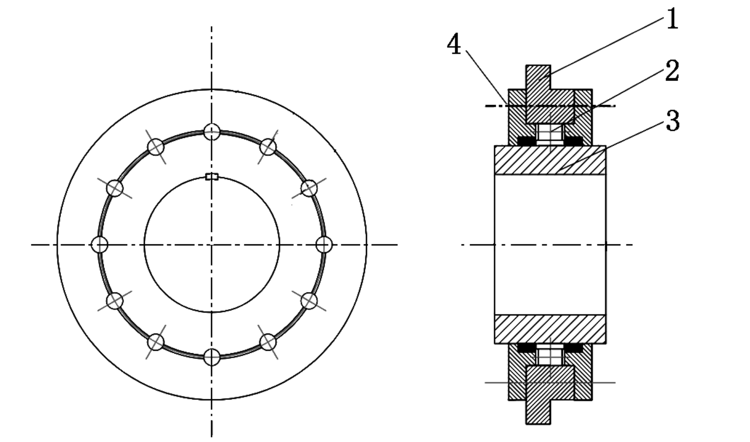
The structure of the casting after setting the machining allowance is shown in Figure 1. The contour size of the casting is 1648 mm × 620 mm × 1077 mm, the volume is 0.251 m³, and the mass of the casting is 1957.8 kg. The maximum wall thickness is 153 mm, and the minimum wall thickness is 30 mm. According to the size characteristics of the high-pressure steam chamber steel casting, from the list of minimum wall thicknesses of sand-cast steel castings in the casting manual, its minimum wall thickness is 20 mm. The analysis result of the wall thickness of the steam chamber casting is shown in Figure 2, which indicates that this casting meets the requirements of the minimum wall thickness and the critical wall thickness.
3. Casting Process Scheme Analysis
The casting process scheme design includes the determination of molding (core) materials, casting pouring position, parting surface, sand core, and process parameters.
3.1 Determination of Pouring Position and Parting Surface
The pouring position of the casting refers to the position of the casting in the mold during pouring. The casting parting surface is the joint surface between the mold elements, which is divided into several parts to facilitate the removal of the pattern. The selection of the parting surface should be as consistent as possible with the pouring position to simplify the casting process and obtain high-quality castings. For the high-pressure steam chamber casting studied in this paper, there are two reasonable pouring positions and parting surfaces: vertical and horizontal. Considering the shape, structure, and size of the casting, if the casting is poured in a vertical position, the height of the sand box will be too high, and the metal liquid will have a great impact on the cavity during filling, resulting in an unstable filling process. At the same time, although selecting the parting surface on the upper surface of the steam chamber base meets the principle of taking the parting surface at the largest section, it is easy to misalign during mold closing. When the casting is in a horizontal pouring position, the largest section can be taken as the parting surface, which is convenient for mold removal. When designing the feeding process, the thick part of the casting is above, which is convenient for placing the riser for feeding. In addition, the horizontal pouring position can also avoid the use of chaplets and simplify the process design. Therefore, the horizontal pouring position and parting surface are adopted in the process design.
3.2 Design of the Mold
The pouring temperature of the steam chamber steel casting is relatively high (about 1580 °C), and the thermal impact of the molten steel on the sand mold is strong. Therefore, the refractory degree requirements for the sand mold and sand core are high. The selected raw sand should have a SiO₂ content of ≥ 97%. Phenolic resin sand is used for molding and core making, and corundum powder alcohol-based paint is selected. The spraying method is adopted, which is easy to operate, has high production efficiency, and is fast and effective. The placement position of the sand core during casting is shown in Figure 4. According to the internal cavity structure of the casting, three sand cores are needed. The left and right parts of the steam chamber cavity are divided into two sand cores (No. 1 and No. 2 sand cores) for casting the steam chamber cavity. For the outer shell hole, to ensure one-time casting, a No. 3 sand core is designed.
3.3 Casting Process Parameters
This steel casting is produced in small batches, and resin self-hardening sand is used for manual molding. The dimensional tolerance grade is CT13 (GB/T 6414 – 2017 “Dimensional Tolerances, Geometric Tolerances, and Machining Allowances for Castings”), and the weight tolerance grade is MT12 (GB/T 11351 – 2017 “Weight Tolerances for Castings”). The weight tolerance value is 8%. To obtain castings with higher dimensional accuracy, the shrinkage rate of the restricted line is 1.8%.
4. Casting Process Design Based on Theoretical Calculation
The pouring temperature of steel castings is high. During the pouring process, the molten steel radiates a large amount of heat to the cavity, and the cavity will expand in volume after being heated by high temperature, resulting in the collapse of the molding sand. In the production process of medium and large castings, if the pouring of molten steel cannot be realized quickly, the thermal radiation of the molten steel will cause serious damage to the sand mold. The pouring system of steel castings generally adopts an open type and is poured with a bottom pouring ladle. This casting is a medium-sized and large casting with a medium structure. Considering the pressure-bearing technical requirements of the casting, the rising speed of the molten steel is increased by 30% – 50% according to the value of complex parts and is taken as vₗ = 35 mm/s.
The pouring time is calculated according to Equation (1). The weight of the molten steel GL is calculated by considering a 7% increase in the weight of the casting due to expansion of the box and the weights of the gating and risering systems. Taking N = 1, n = 1, and the diameter of the ladle nozzle as 70 mm, the pouring speed vₚₐₖ = 120 kg/s. The theoretically calculated pouring time t = 17.46 s, and combined with the actual casting production, the pouring time can be set to 18 s.
The liquid level rising speed vₗ is calculated according to Equation (2) for verification. The height hc of the casting at the pouring position is 620 mm, and the calculated liquid level rising speed vₗ = 35.5 mm/s > 35 mm/s, which meets the requirements.
An open pouring system is adopted, and the proportional relationship of the cross-sectional areas of each unit can be 1.0:(1.8 – 2.0):(1.8 – 2.0):(2.0 – 2.5). Since the diameter of the ladle nozzle is 70 mm (> φ55 mm), a refractory brick tube pouring system is used.
The minimum residual head hm is calculated according to Equation (3) to ensure that it is sufficient. When the length of the sprue is 250 mm, hm = 83 mm, L = 790 mm, and α = 6° is taken according to the value of L and the wall thickness of the casting. It satisfies hm ≥ L tanα, indicating that the minimum residual head of this design scheme meets the requirements.
The preliminary designed pouring system is shown in Figure 5. Based on the structural characteristics of the circular cavity of the steam chamber part, three evenly distributed ingates are set at the parting surface of the casting pouring system to make the temperature distribution in the horizontal direction as uniform as possible.
5. ProCAST Numerical Simulation and Improvement
5.1 Determination of Simulation Initial Parameters
According to the above preliminary designed process scheme, the ProCAST numerical simulation software is used to simulate the filling and solidification processes of the high-pressure steam chamber casting. The liquidus temperature is known to be 1501 °C, and the pouring temperature is approximately taken as 1600 °C in the simulation. The grid division of the casting process scheme system model is shown in Figure 6. The pouring time is 18 s, and the heat transfer coefficient between the metal and the sand mold h = 750 W/(m²·K).
5.2 Simulation Result Analysis
The numerical simulation results of the metal liquid filling process are shown in Figure 7. During the filling process, there is no underpouring in the casting, and the complete filling can be achieved by using the designed casting process scheme.
The defect prediction of the casting process simulation results is shown in Figure 8. It can be seen that there are very large shrinkage cavity defects in the thick part of the steam chamber base, and obvious shrinkage porosity and shrinkage cavity phenomena also exist at the transition connection between the steam chamber partition and the top boss wall of the casting. The reasons for the shrinkage porosity and shrinkage cavity in the thicker parts of the casting are that the wall thicknesses of the steam chamber base and the top boss are too thick, resulting in hot spots; and they are at a higher horizontal level in this pouring position, with slow heat dissipation and the existence of isolated liquid phase regions, which often lead to defects and affect the casting quality.
5.3 Process Scheme Improvement
The above simulation results show that the shrinkage porosity and shrinkage cavity are mainly concentrated in the thick parts on both sides of the steam chamber base and the partitions at the two air inlets of the steam chamber and the top boss. Therefore, risers are preferentially set at the four positions shown in Figure 9 to improve the feeding of the casting. The riser modulus at these four positions is calculated by the modulus method, and the size of each riser can be obtained by referring to the casting manual.
On the basis of setting the risers, chills are placed at the positions with obvious shrinkage porosity for process improvement. The placement positions of the chills are shown in Figure 10. Chills are set in the inner cavity at the thick position of the steam chamber base and at the partitions of the two steam ports, respectively. Following the principle of sequential solidification, it is hoped that the parts where the chills are set will solidify before the risers, and most of the solidification defects will be concentrated in the risers.
The improved process scheme is modeled in three dimensions and then simulated by ProCAST numerical simulation software. The simulation results are shown in Figure 11. It can be seen that the shrinkage cavity situation of the casting has been significantly improved, the shrinkage cavity has been transferred to the risers, and there is no obvious shrinkage cavity in the casting. The total shrinkage porosity is 2.71%. However, due to the placement of the chills, the molten metal at the steam chamber partition solidifies earlier than the surrounding area, and the molten metal at the boss flows towards the partition, resulting in the shrinkage porosity at the boss extending from top to bottom and being deeper than that before the chills are set.
In the subsequent improvement process, measures such as changing the size and number of risers and their positions, changing the size of the chills, and designing insulated risers can be taken to eliminate the shrinkage porosity defects, ensure that the top boss of the steam chamber will not collapse due to solidification defects, and thus improve the casting yield.
6. Conclusion
In this paper, the casting process scheme of the high-pressure steam chamber is analyzed based on its material and structural characteristics. The preliminary casting process scheme of the high-pressure steam chamber steel casting is designed through theoretical calculation, and the filling and solidification process of the original casting process scheme is simulated by using ProCAST casting simulation software. The pouring temperature is set to 1600 °C, the pouring time is 18 s, and the heat transfer coefficient between the metal and the sand mold h = 750 W/(m²·K). Based on the types and positions of the casting defects, the original process scheme is improved.
Risers are designed at the top boss and the thick parts on both sides of the base of the steam chamber, and external chills are placed at the partitions on both sides of the steam port and the positions closest to the base defect in the steam chamber cavity. The improved process is simulated again. The simulation results show that the improved process scheme eliminates the shrinkage cavity defects, and the total shrinkage porosity is 2.71%, providing a process design idea for further completely eliminating the shrinkage porosity defects.