
In the production of diesel engine components, cylinder liners are critical sand casting parts that demand exceptional surface quality, mechanical properties, and microstructural integrity. Traditionally, centrifugal casting is preferred for these sand casting parts due to its ability to yield fine-grained structures and minimal defects. However, for large cylinder liners with bore diameters exceeding 500 mm, centrifugal casting poses significant challenges in equipment stability and safety. Consequently, sand casting, particularly using resin-bonded sand, becomes a viable alternative. This article explores my firsthand experience and technical insights into developing a resin sand casting process for a large cylinder liner with a bore diameter of 580 mm, weighing approximately 2500 kg and measuring 1910 mm in length. The successful implementation of this process highlights the adaptability of sand casting parts in heavy-duty applications.
The cylinder liner in question is a substantial sand casting part made from alloyed special cast iron. Its dimensions include an outer diameter nearing 800 mm at the large end, 690 mm at the small end, and an inner diameter of 560 mm, with a maximum wall thickness of 120 mm. Such thick-walled sand casting parts necessitate meticulous process control to avoid defects like shrinkage porosity, sand inclusion, and undesirable microstructure. The use of resin sand molds, combined with a top-pouring rain gating system, was employed to achieve a sound casting. Below, I delve into the technical difficulties encountered and the systematic measures adopted to overcome them, emphasizing the role of resin sand in fabricating high-integrity sand casting parts.
Analysis of Process Challenges in Resin Sand Casting
Resin-bonded sand offers numerous advantages, such as excellent dimensional accuracy, good collapsibility, and high strength. However, its properties—including superior insulation, low thermal conductivity, and susceptibility to erosion—pose specific challenges when casting large, thick-walled sand casting parts like cylinder liners. These challenges must be addressed to ensure the quality of the final sand casting parts.
1.1 Susceptibility to Sand Erosion Leading to Defects
The rain gating system, where molten metal is poured through multiple small holes in the sprue, is effective for slag trapping and reducing turbulence. It facilitates rapid mold filling and promotes directional solidification from the bottom upward, which is crucial for sand casting parts. Nonetheless, resin sand’s resistance to erosion is relatively poor. Even with rain gating, the high drop height (nearly 2 meters) and prolonged metal flow can cause erosion of the mold and cores, resulting in sand inclusion, burnt-on sand, or penetration defects. This is a common issue in large sand casting parts where metal velocity and thermal effects are pronounced.
The erosion risk can be quantified by considering the kinetic energy of the molten metal stream. The force exerted on the mold surface is proportional to the density of the metal, the flow velocity, and the impact area. For a rain gating system, the velocity at the gate outlets can be approximated using Torricelli’s theorem: $$ v = \sqrt{2gh} $$ where \( v \) is the velocity, \( g \) is gravitational acceleration, and \( h \) is the metallostatic head height. For a head height of 2000 mm, the velocity approaches 6.26 m/s, sufficient to dislodge sand grains if the mold surface is not adequately reinforced.
1.2 Difficulties in Ensuring Microstructure and Mechanical Properties
Large cylinder liners, as critical sand casting parts, require stringent microstructural and mechanical specifications: ferrite content ≤3%, hard phases (e.g., phosphide eutectic and alloy carbides) finely and uniformly distributed, and a hardness range of 190–240 HB. The slow cooling inherent in resin sand molds—due to their low thermal conductivity—prolongs solidification, favoring the growth of columnar grains and coarse graphite. This can lead to excessive ferrite, coarse hard phases, shrinkage porosity, and lower hardness, compromising the performance of these sand casting parts.
The solidification time for a sand casting part can be estimated using Chvorinov’s rule: $$ t = B \left( \frac{V}{A} \right)^n $$ where \( t \) is solidification time, \( V \) is volume, \( A \) is surface area, \( B \) is a mold constant, and \( n \) is an exponent (typically 2 for sand molds). For thick sections, \( V/A \) is large, resulting in extended solidification. In resin sand, the mold constant \( B \) is higher due to its insulating properties, further slowing cooling. This exacerbates microstructural coarsening in sand casting parts.
To summarize these challenges, the table below outlines key issues and their implications for resin sand casting of large cylinder liners:
| Challenge | Root Cause | Potential Defects in Sand Casting Parts |
|---|---|---|
| Sand erosion | Low erosion resistance of resin sand; high metal velocity | Sand inclusion, burnt-on sand, surface roughness |
| Slow cooling | Low thermal conductivity of resin sand; thick sections | Coarse graphite, excessive ferrite, shrinkage porosity, low hardness |
| Microstructural control | Prolonged solidification; insufficient inoculation | Non-uniform hard phases; out-of-spec ferrite content |
Process Measures for Successful Casting
To address these challenges, a comprehensive set of process measures was implemented, focusing on both mold integrity and metallurgical control. These measures are essential for producing high-quality sand casting parts via resin sand molds.
2.1 Measures to Prevent Sand Erosion
Preventing erosion is critical to maintaining the surface quality of sand casting parts. The following steps were taken:
a. Controlled Pouring Time: The pouring time was strictly limited to within 100 seconds. Shorter pouring times reduce the duration of metal flow and minimize continuous impact on the mold. The pouring rate \( Q \) can be calculated as: $$ Q = \frac{W}{\rho t} $$ where \( W \) is the casting weight, \( \rho \) is metal density, and \( t \) is pouring time. For a 2500 kg casting and iron density of 7000 kg/m³, the required flow rate is approximately 0.0357 m³/s. This necessitates appropriately sized gating systems to achieve rapid filling without excessive turbulence.
b. Enhanced Mold and Core Compaction: Unlike simple filling, the resin sand was manually rammed during molding and core-making to increase compactness. Higher compaction improves erosion resistance by reducing permeability and increasing green strength. The compaction density \( \rho_s \) can be expressed as: $$ \rho_s = \frac{m_s}{V_s} $$ where \( m_s \) is sand mass and \( V_s \) is volume. Practical tests showed that rammed molds had a density increase of 10–15% over loosely filled ones, significantly improving durability for sand casting parts.
c. High-Quality Coating Layers: A dual-coating system was applied: first, a water-based graphite coating, oven-dried, followed by an alcohol-based zircon flour coating applied before mold assembly. Coating thickness was controlled at 0.5–0.8 mm. Coatings act as a barrier, reducing metal penetration and erosion. The effectiveness of a coating can be related to its refractory index \( R \), which for zircon flour is high, enhancing protection for sand casting parts.
d. Level Mold Assembly: The bottom mold was precisely leveled using a spirit level to ensure vertical alignment of the mold cavity. This prevents asymmetric metal flow that could locally scour the mold walls. Inclination angles as small as 2° can cause significant flow deviation, increasing erosion risk in sand casting parts.
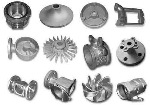
The image above illustrates a typical large sand casting part produced via resin sand molding, showcasing the complexity and scale involved. Such sand casting parts require meticulous process design to achieve defect-free outcomes.
2.2 Measures to Guarantee Microstructure and Mechanical Properties
Metallurgical controls are paramount for meeting the stringent requirements of cylinder liners, which are high-performance sand casting parts. The following measures were implemented:
a. High-Temperature Holding and Superheating: The molten iron was superheated to above 1480°C and held for 10 minutes before tapping. This practice purifies the melt by promoting slag formation and dissolution of inclusions, and it refines the grain structure by increasing undercooling potential. The effect of superheating on grain size \( d \) can be described by: $$ d = k \cdot \Delta T^{-n} $$ where \( \Delta T \) is undercooling, and \( k, n \) are constants. Higher superheating enhances undercooling, leading to finer grains in sand casting parts.
b. Alloying with Tin (Sn): Tin was added at 0.05–0.1% to stabilize pearlite without forming free cementite. Sn promotes fine graphite and increases the high-temperature stability of pearlite, counteracting the slow cooling of resin sand. The addition was made via small Sn blocks added to the stream along with inoculant. The effect of Sn on hardenability can be approximated by: $$ H = f(\%Sn) \cdot C_{eq} $$ where \( H \) is hardenability, and \( C_{eq} \) is carbon equivalent. Sn significantly elevates \( H \), ensuring adequate hardness in thick-section sand casting parts.
c. Enhanced Inoculation Practices: Inoculation was performed in two stages: (1) stream inoculation during tapping, and (2) late inoculation by adding 0.2% ferrosilicon (as浮硅, i.e., floating silicon pieces >20 mm in diameter) onto the ladle surface after slag removal, covered with charcoal dust. This double inoculation enhances graphite nucleation, promoting type A graphite and reducing ferrite. The nucleation rate \( N \) can be expressed as: $$ N = N_0 \exp\left(-\frac{\Delta G^*}{kT}\right) $$ where \( \Delta G^* \) is activation energy, \( k \) is Boltzmann’s constant, and \( T \) is temperature. Inoculation lowers \( \Delta G^* \), increasing \( N \) for finer graphite in sand casting parts.
d. Optimized Pouring Temperature: The pouring temperature was carefully controlled to 1320 ± 10°C. Lower pouring temperatures reduce the thermal load on the mold, accelerating cooling and minimizing graphite coarsening and ferrite formation. It also reduces erosion potential. The relationship between pouring temperature \( T_p \) and cooling rate \( \dot{T} \) can be modeled as: $$ \dot{T} \propto \frac{T_p – T_m}{\delta^2} $$ where \( T_m \) is mold temperature, and \( \delta \) is mold thickness. Lower \( T_p \) increases \( \dot{T} \), benefiting the microstructure of sand casting parts.
The table below summarizes key process parameters and their effects on the quality of sand casting parts:
| Process Parameter | Target Value | Role in Sand Casting Parts Quality |
|---|---|---|
| Pouring time | ≤ 100 s | Minimizes erosion; ensures rapid filling |
| Mold coating thickness | 0.5–0.8 mm | Enhances erosion resistance; improves surface finish |
| Superheating temperature | ≥ 1480°C | Refines grains; purifies melt |
| Tin addition | 0.05–0.1% | Stabilizes pearlite; fine-tunes hardness |
| Inoculation amount | 0.2% floating Si | Promotes type A graphite; reduces ferrite |
| Pouring temperature | 1320 ± 10°C | Accelerates cooling; minimizes defects |
Detailed Technical Expansions on Resin Sand Casting
To further elucidate the process, let’s delve into the underlying principles and calculations involved in producing large sand casting parts via resin sand. This expansion aims to provide a comprehensive understanding suitable for foundry engineers.
3.1 Thermal Dynamics in Resin Sand Molds
The thermal behavior of resin sand molds significantly influences the solidification of sand casting parts. The heat transfer can be modeled using Fourier’s law in one dimension: $$ q = -k \frac{dT}{dx} $$ where \( q \) is heat flux, \( k \) is thermal conductivity, and \( \frac{dT}{dx} \) is temperature gradient. Resin sand has a low \( k \) value (typically 0.5–1.0 W/m·K), leading to shallow temperature gradients and slow cooling. For a cylindrical sand casting part like a liner, the radial heat flow is dominant. The temperature distribution \( T(r,t) \) can be described by the heat conduction equation: $$ \frac{\partial T}{\partial t} = \alpha \left( \frac{\partial^2 T}{\partial r^2} + \frac{1}{r} \frac{\partial T}{\partial r} \right) $$ where \( \alpha \) is thermal diffusivity. Solving this with boundary conditions helps predict solidification fronts and cooling rates for sand casting parts.
To mitigate slow cooling, chills or cooling fins can be incorporated into the mold design. However, for this cylinder liner, metallurgical adjustments (e.g., Sn addition) were preferred to avoid complexity. The effectiveness of such adjustments can be quantified by the equivalent carbon content \( C_{eq} \), calculated as: $$ C_{eq} = \%C + 0.33(\%Si) + 0.33(\%P) – 0.027(\%Mn) + 0.4(\%S) + \text{alloy factors} $$ For alloyed iron, Sn contributes to pearlite stability, effectively raising the critical cooling rate to avoid ferrite.
3.2 Gating System Design for Rain Pouring
The rain gating system is crucial for directional solidification in tall sand casting parts. The design involves multiple gates arranged circumferentially at the top of the mold. The total gate area \( A_g \) must satisfy: $$ A_g = \frac{Q}{v_g} $$ where \( v_g \) is the desired gate velocity, typically kept below 0.5 m/s to minimize erosion. For a pouring rate \( Q \) of 0.0357 m³/s, \( A_g \) should be at least 0.0714 m². This area was distributed over 12 gates, each of diameter 30 mm, ensuring uniform filling.
The metallostatic pressure \( P \) at the bottom of the casting is: $$ P = \rho g h $$ where \( h \) is the height of the metal column. For \( h = 1910 \) mm, \( P \) is about 0.13 MPa, which can cause mold wall deformation if the sand strength is insufficient. Resin sand’s high compressive strength (often >1 MPa) withstands this pressure, but erosion remains a concern. Therefore, coating and compaction are vital for these sand casting parts.
3.3 Microstructural Evolution and Control
The microstructure of cast iron in sand casting parts is governed by cooling rate and composition. The ferrite content \( F \) can be estimated using empirical relations: $$ F = a – b \cdot \ln(\dot{T}) + c \cdot \%Si $$ where \( \dot{T} \) is cooling rate, and \( a, b, c \) are constants. Slow cooling from resin sand increases \( F \), hence alloying and inoculation are used to suppress it. The hard phase distribution is influenced by the solidification time \( t_s \). For phosphide eutectic, the interphase spacing \( \lambda \) scales with \( t_s \): $$ \lambda = k_\lambda t_s^{1/3} $$ Shorter \( t_s \) yields finer hard phases. By lowering pouring temperature and using inoculants, \( t_s \) is reduced, benefiting sand casting parts.
Furthermore, the hardness \( HB \) of the casting can be correlated with microstructure: $$ HB = f(V_p, V_f, V_c) $$ where \( V_p \) is pearlite volume, \( V_f \) is ferrite volume, and \( V_c \) is carbide volume. Through Sn addition and controlled cooling, \( V_p \) is maximized, and \( V_f \) minimized, achieving the target hardness of 190–240 HB for these sand casting parts.
3.4 Quality Assurance and Testing
Post-casting, the cylinder liner underwent non-destructive testing (ultrasonic and radiographic) and destructive testing (tensile, hardness, and microstructural analysis). The results confirmed the absence of shrinkage porosity, sand inclusion, and other defects common in sand casting parts. The microstructure showed fine type A graphite, pearlite matrix with ferrite below 2%, and uniformly distributed hard phases. Hardness measurements across sections averaged 220 HB, meeting specifications.
The success of this process underscores the feasibility of resin sand casting for large, high-quality sand casting parts. It also opens avenues for optimizing other heavy-section sand casting parts using similar methodologies.
Conclusion
In summary, the resin sand casting process for large cylinder liners, as critical sand casting parts, requires a holistic approach addressing both mold-related and metallurgical challenges. By implementing controlled pouring times, enhanced mold compaction, dual-layer coatings, precise leveling, high-temperature melting, tin alloying, enhanced inoculation, and optimized pouring temperatures, we achieved a defect-free casting with desired microstructure and mechanical properties. The process leverages the advantages of resin sand while mitigating its drawbacks through careful engineering. This experience demonstrates that with appropriate measures, resin sand casting can reliably produce large, complex sand casting parts for demanding applications, contributing to the advancement of foundry technology for heavy-duty components.