
In the production of sand casting parts using green sand molds, defects such as sand inclusions and gas holes are prevalent and challenging. Traditionally, foundry engineers rely heavily on empirical knowledge for diagnosis and remediation, leading to subjective and often inconsistent solutions. Since 2011, a collaborative project was initiated with a university to employ Scanning Electron Microscopy (SEM) combined with Energy-Dispersive X-ray Spectroscopy (EDS) for defect analysis. This technique allows for high-magnification surface examination and micro-area qualitative/semi-quantitative chemical analysis, providing objective data to quickly identify the root cause and implement effective countermeasures for defects in sand casting parts.
The SEM/EDS Analytical Approach
The integration of SEM and EDS offers a powerful tool for the metallurgical investigation of defects in sand casting parts. SEM provides detailed topographical images of defect surfaces at magnifications far beyond optical microscopy, revealing features like embedded sand grains, pore morphology, or micro-cracks. EDS complements this by identifying the elemental composition of specific micro-areas within the defect. For instance, a high concentration of silicon (Si) and oxygen (O) indicates silica sand inclusion, while the presence of carbon (C) and oxygen might suggest a gas hole related to organic binders or moisture. This data-driven method moves defect analysis from conjecture to scientific verification.
Application of SEM/EDS in Sand Inclusion Analysis
Phenomenon: Surface cavities or holes were observed on finished sand casting parts.
Production Context: The sand casting parts were gray iron, weighing approximately 15 kg each, produced on an HWS molding line using cold-box cores and an Eirich sand mixer.
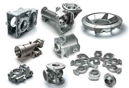
Green Sand Properties and Granulometry: Initial analysis focused on the condition of the molding sand, which is fundamental to the integrity of sand casting parts.
| Parameter | Unit | Value |
|---|---|---|
| Moisture | % | 3.6 |
| Active Bentonite | % | 6.51 |
| Loss on Ignition (LOI) | % | 5.4 |
| Green Compressive Strength | kPa | 208 |
| Compactability | % | 26 |
| Permeability Number | – | 110 |
| AFS Grain Fineness Number | – | 57.81 |
The low active bentonite content (6.51%) was a primary concern. The ratio of compactability to moisture (C/W), a key indicator of mulling efficiency and sand “temper,” was calculated as:
$$ \text{C/W Ratio} = \frac{\text{Compactability (\%)}}{\text{Moisture (\%)}} = \frac{26}{3.6} \approx 7.2 $$
A ratio below 10 typically indicates poor clay activation, leading to weak bonding and low deformation resistance, making the mold susceptible to erosion and sand inclusion in sand casting parts.
The sand grain distribution was also problematic:
| Sieve (Mesh) | Retained (%) |
|---|---|
| 6 | 0.00 |
| 20 | 0.02 |
| 40 | 0.11 |
| 70 | 26.96 |
| 140 | 41.23 |
| 270 | 19.67 |
| Pan | 4.54 |
The distribution showed a very high peak on the 140-mesh sieve (>40%), with disproportionate differences between adjacent sieves. This non-ideal distribution compromises sand flowability and packability, resulting in less dense molds that can easily break down during pouring, leading to sand inclusions in the final sand casting parts.
SEM/EDS Analysis of the Defect: A sample from the cavity was analyzed. SEM imaging clearly revealed the distinct morphological features of sand grains within the defect area. Subsequent EDS point analysis on the bright, granular particles within the cavity provided definitive chemical evidence.
The EDS spectrum showed dominant peaks for Oxygen (O) and Silicon (Si), with a smaller peak for Aluminum (Al). This elemental signature is conclusive for silica-based molding sand, confirming the defect as a sand inclusion rather than a gas hole. The semi-quantitative results aligned with the typical composition of used green sand.
Corrective Actions Implemented:
1. Increased bentonite additions to raise the active bentonite level to between 7.5% and 8.0%.
2. Adjusted carbonaceous additive (coal dust/seacoal) additions to reduce the LOI/Active Bentonite ratio from approximately 82% to near 60%.
3. Optimized mulling parameters to achieve a C/W Ratio close to 10, improving clay coating and sand plasticity. The desired sand consistency was “firm but not sticky.”
4. Modified the system sand by adding new sand to reduce the retention on the 140-mesh sieve below 40% and to achieve a more progressive gradient between sieves (differences of 8-12%), thereby enhancing flowability and mold density for sand casting parts.
These measures successfully eliminated the sand inclusion defect.
Application of SEM/EDS in Gas Hole Analysis
Production Context: Sand casting parts (approx. 120 kg mold weight) were produced on an ACE molding line with a pouring temperature range of 1380-1410°C. Defects appeared as subsurface blowholes or surface pits.
Green Sand Property Trends: Monitoring data revealed a concerning trend in sand properties over time, crucial for understanding defects in sand casting parts.
| Parameter | Unit | Sample Date 1 | Sample Date 2 | Sample Date 3 | Sample Date 4 |
|---|---|---|---|---|---|
| Moisture | % | 2.76 | 2.77 | 2.78 | 2.80 |
| Active Bentonite | % | 7.30 | 6.93 | 7.21 | 7.86 |
| LOI | % | 3.66 | 3.50 | 4.52 | 4.69 |
| Green Compressive Strength | kPa | 215 | 205 | 200 | 206 |
| Permeability Number | – | 93 | 95 | 85 | 84 |
| AFS Grain Fineness | – | 56.71 | 56.69 | 58.74 | 59.64 |
The data indicated a gradual increase in AFS Grain Fineness Number (meaning the sand became finer on average) and LOI, coupled with a decrease in permeability. The permeability (P) can be conceptually related to grain size and void space:
$$ P \propto \frac{d^2}{L} $$
where \(d\) is the effective grain diameter and \(L\) is the sample length. Finer sand and higher fines content (increasing LOI) reduce \(d\) and clog pores, leading to lower \(P\). This creates a condition where gases generated during pouring have greater difficulty escaping, increasing the risk of gas holes in sand casting parts.
Defect Sample Analysis via SEM/EDS: Three different defect samples from the problematic sand casting parts were analyzed.
Sample 1 (Likely Gas Hole): SEM images showed a relatively clean cavity wall with minimal adherent inclusions. EDS analysis of the cavity surface detected primarily iron (Fe) with some manganese (Mn) and carbon (C), consistent with the base metal. The lack of foreign elements like Si or Al from sand suggested a gas pressure defect, likely from moisture vaporization or core gas.
Sample 2 (Slag-related Gas Hole): SEM revealed some non-metallic inclusions within the pore. EDS identified these inclusions as containing Silicon (Si), Oxygen (O), and Iron (Fe), suggesting the presence of oxidized slag compounds (e.g., silicates, iron oxides).
Sample 3 (Slag-related Gas Hole): Similar to Sample 2, SEM showed inclusions, and EDS confirmed a high content of Silicon (Si) and Oxygen (O).
The SEM/EDS analysis confirmed that all three defects were gas-related, with two being specifically slag-gas holes. These defects often occur at the top of the casting or near ingates—areas where metal flow turbulence or first-metal contact promotes dross formation and gas entrapment in sand casting parts.
The formation mechanism for such slag-gas holes involves oxidation of alloying elements and reaction with carbon:
$$ \text{Mn} + \text{O} \rightarrow \text{MnO} $$
$$ \text{Fe} + \text{O} \rightarrow \text{FeO} $$
$$ \text{Si} + 2\text{O} \rightarrow \text{SiO}_2 $$
These oxides form a slag. This slag can then react with carbon in the iron to generate gas:
$$ \text{FeO-MnO-SiO}_2 (\text{slag}) + \text{C} \rightarrow \text{CO} \uparrow + \text{Fe-Mn-Si melt} $$
This reaction is exacerbated when the manganese content exceeds ~0.75% and pouring temperatures are below approximately 1400°C.
Corrective Actions Implemented:
1. Optimized sand muller parameters to ensure the C/W Ratio was consistent from the start to the end of the mulling cycle, minimizing free water.
2. Reduced the addition rates of inoculant and spheroidizer to lower the potential for dross formation from oxidized alloys in the production of these ductile iron sand casting parts.
3. Strictly controlled the moisture content of resin-coated sand cores to below 0.3% before setting to minimize a major gas source.
4. Slightly increased the pouring temperature where possible to improve metal fluidity and slag buoyancy.
5. Differentiated squeeze pressures between cope and drag molds to optimize mold hardness distribution.
These integrated actions targeting both sand properties and metal treatment effectively controlled the gas hole defect.
Key Learnings and Formula for Sand Control
The systematic analysis of defects in sand casting parts leads to several critical conclusions and the establishment of key control parameters. Proper green sand control is paramount. Two derived ratios are exceptionally useful for day-to-day monitoring and prevention of common defects in sand casting parts.
1. Compactability/Moisture Ratio (C/W): This is a direct indicator of mulling efficiency and the “health” of the bentonite bonding film.
$$ R_{C/W} = \frac{C}{M} $$
where \(C\) is Compactability (%) and \(M\) is Moisture (%). A ratio between 9.5 and 11.5 generally indicates well-mulled sand with good plasticity and strength, reducing the risk of sand inclusions and erosion defects in sand casting parts.
2. LOI/Active Bentonite Ratio: This ratio helps balance the carbonaceous materials (which generate a reducing atmosphere and improve surface finish) with the active clay (which provides strength).
$$ R_{L/A} = \frac{LOI}{A} \times 100\% $$
where \(LOI\) is Loss on Ignition (%) and \(A\) is Active Bentonite (%). Maintaining this ratio between 50% and 70% is often ideal. A ratio that is too high can lead to excessive gas generation and lowered strength, promoting gas holes and weak molds for sand casting parts.
3. Thermal Strength Relationship: The hot properties of sand, critical for resisting metal pressure and heat, are related to the active bentonite content. The green sand’s resistance to scabbing and erosion can be inferred from its hot strength, which correlates with the active clay. A simplified expression for the dependence of a key thermal property, like the Thermal Wet Tensile Strength (TWTS), on active bentonite can be modeled as:
$$ \text{TWTS} \propto k \cdot (A – A_0)^n $$
where \(k\) is a constant, \(A\) is the active bentonite content, \(A_0\) is a threshold content below which strength is negligible, and \(n\) is an exponent typically less than 1, reflecting the non-linear relationship common in the bonding of sand casting parts molds.
| Defect Type | Key Sand Indicators | Typical EDS Signature | Primary Corrective Focus |
|---|---|---|---|
| Sand Inclusion | Low Active Bentonite, Low C/W Ratio, Poor Grain Distribution | High Si, O, Al (Sand) | Increase Active Clay, Improve Mulling, Adjust Grain Distribution |
| Gas Hole (Sand/Moisture) | High Moisture, High LOI, Low Permeability | High Fe, C (Base Metal) possibly O | Control Moisture & LOI, Improve Permeability, Dry Cores |
| Slag-Gas Hole | Sand properties may be secondary; Metal quality is key. | High Si, O, Fe, Mn (Oxides/Slag) | Metal Treatment: Control Pouring Temp, Reduce Oxidation, Improve Skimming |
In conclusion, the adoption of SEM/EDS analysis transforms the troubleshooting of sand casting parts defects from an art into a science. It provides unambiguous evidence to distinguish between visually similar defects like sand holes and gas holes. This diagnostic power, when combined with fundamental understanding and control of green sand ratios (C/W and LOI/Active Bentonite) and metal processing parameters, enables the implementation of precise, effective, and economical solutions to enhance the quality and yield of sand casting parts. The continuous monitoring of these parameters forms the backbone of a robust and preventive quality assurance system for any green sand foundry producing sand casting parts.