
steam turbine relies on the high-speed flow of steam to expand in the nozzle chamber of the turbine, thereby converting it into kinetic energy. During service, the high-pressure inner cylinder of a steam turbine must withstand various complex loads and tests such as low and high cycle fatigue, high flow velocity, and high impact in a high-temperature environment. Due to the expansion of steam in the nozzle chamber inside the steam turbine, the channels and gaps in the nozzle chamber are designed to be particularly narrow, which poses great difficulties for the casting process and post pouring cleaning process. Therefore, high requirements are placed on the internal quality and comprehensive mechanical properties of steam turbines, and casting process design and production operations pose a significant challenge for sand casting manufacturers.
1. Casting requirements and sand sticking issues
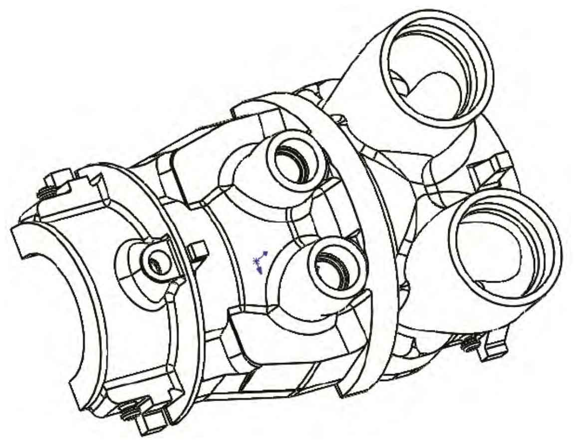
The structure of the high-pressure inner cylinder of the ultra supercritical steam turbine developed by the sand casting manufacturer is shown in Figure 1, with a contour size of 4380 mm x 196 mm x 2800 mm and a material of G-X12CrMoWVNbN10. Sand casting manufacturers develop full body ultrasonic testing for steel castings, with Level 1 acceptance at the cylinder mating surface, Level 2 acceptance at the nozzle chamber, and Level 3 acceptance at other parts.
When sand casting manufacturers produce steel castings, due to the high pouring temperature of the steel liquid, the steel castings require a large amount of steel liquid, a long pouring time, a high metal static head, and strong thermal, mechanical, and chemical reactions. Under the continuous erosion of the steel liquid at high temperature for a long time, metal infiltration and sand sticking occur. FeO in the steel liquid reacts with chromite ore sand to form a Fe-Si-Cr mixture, resulting in serious sand sticking phenomenon, Not only does it affect the surface quality of steel castings, but it also poses difficulties for sand casting manufacturers in later cleaning.
2. Analysis and improvement measures for sand sticking defects
2.1 Analysis of sand sticking defects
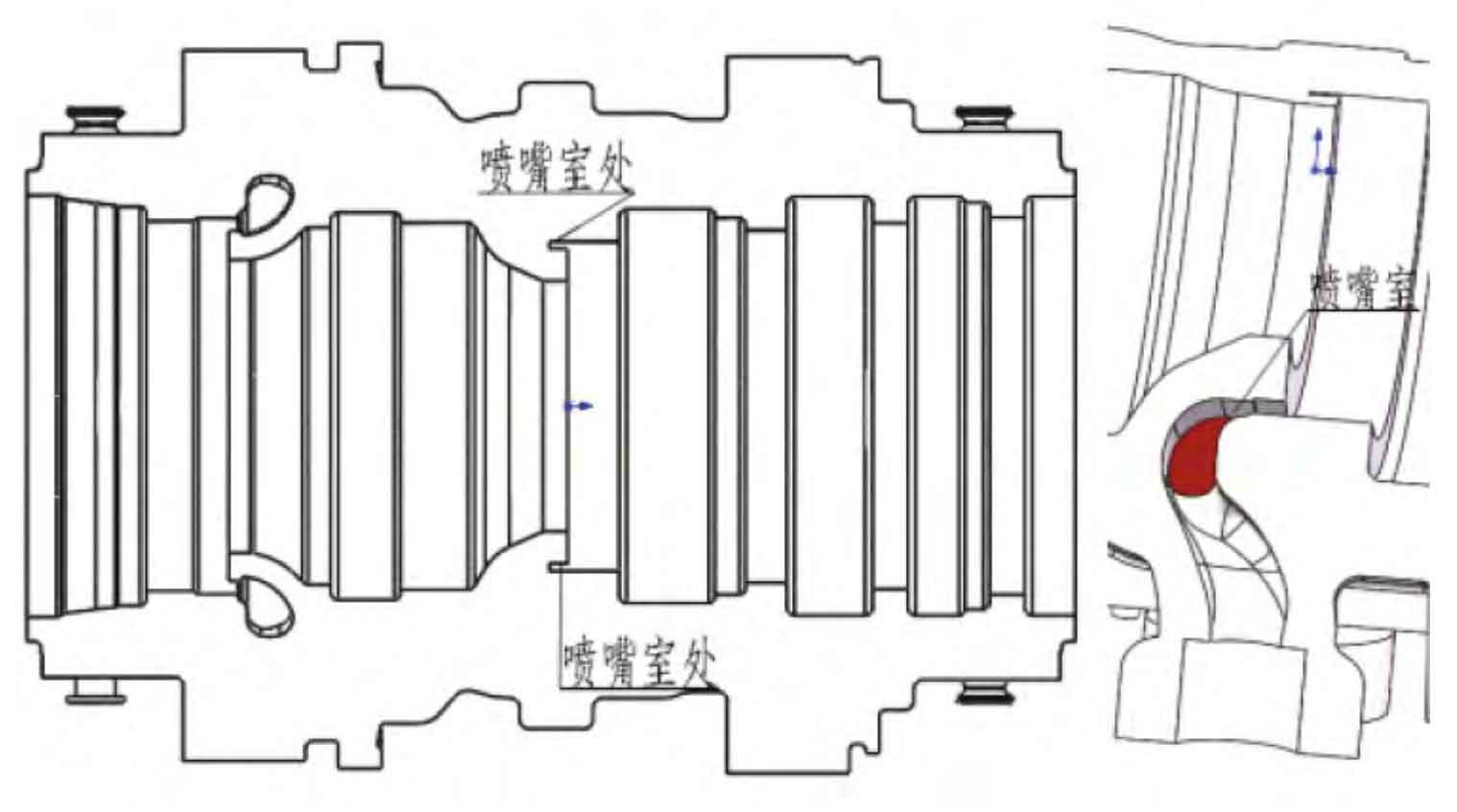
The internal nozzle chamber structure of the high-pressure inner cylinder is shown in Figure 2. From the figure, it can be seen that the minimum thickness of the sand core at the nozzle chamber is 15 mm, and the core strength is very low. During the pouring process, excessive temperature and overheating can lead to the risk of sand sticking or the sand core being washed away by the steel liquid. To prevent sand sticking, the pouring temperature can be lowered within the theoretical allowable range. However, the range of pouring temperature that can be lowered is limited and cannot effectively solve the problem of sand sticking.
During the process design of high-pressure inner cylinder steel castings, the disconnection is shown in Figure 3. The sand casting manufacturer produces steel castings in two sections to enhance the strength of the sand core in this area. The cylinder and half ring are welded and formed after processing the groove.
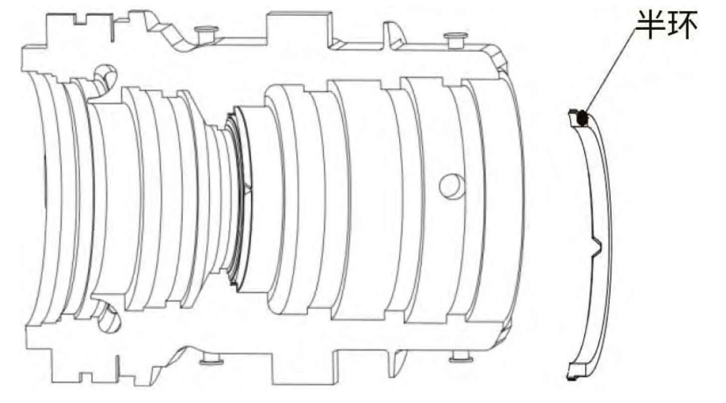
The sand casting manufacturer designed this process plan to effectively increase the strength of the sand core at the nozzle chamber, but the anti sticking sand effect is not significant. Moreover, welding processes have been added, production costs have increased, and the production cycle of steel castings has been extended. Therefore, a more optimal process solution should be sought.
2.2 Improvement measures
The air cooling system is an extension of the heat shock cooling thinking. The use of an air cooling system can remove some heat, reduce the temperature of the steel liquid in contact with the core, and prevent the occurrence of sand sticking. Based on the structure of this cylinder, there is a rib plate in the middle of the nozzle chamber, so the air cooling system is designed as two parts on the left and right, avoiding the rib plate. The setting of the air cooling system is shown in Figure 4.
Sand casting manufacturers need to quantitatively calculate the air cooling process to ensure cooling effectiveness. Firstly, calculate the amount of heat that can be absorbed by this processing theory, and then ensure that the heat released by the air cooling system is greater than this theoretical heat to achieve the purpose of forced cooling.
According to the law of conservation of energy: Δ U=Q-W
In the formula, Δ U is the internal energy increment of the system, Q is the heat absorbed by the system from the environment during this process, and W is the work done by the system to the environment during this process. Δ U is independent of the process and only depends on the initial and final states.
Assuming that the system does 0 work on the environment, then Δ U=Q.
The calculation of convective heat transfer is based on Newton’s formula: Q=A αΔ T
In the formula:
Q – heat flow rate of convective heat transfer, W;
A – Wall heat transfer area, m2;
Δ T – temperature difference between fluid and wall, ℃;
α — Convective heat transfer coefficient, W/(m ^ 2 · ℃).
Temperature difference inside and outside the cooling pipe Δ T=865 ℃, Q=3 130.59 W/m2, which means the theoretical specific heat passed during the pouring process here is 3 130.59 W/m2.
Recalculate the actual specific heat that the air cooling system can carry away: the measured compressed air flow rate of 0.7 MPa is 500 L/min; Adopting ϕ 25 mm steel pipe, according to the table, the single pipe air supply v of the steel pipe is 2.5 m/s, and the specific heat that can be carried away here is Q=Cm Δ T=5 543.85 W/m ^ 2, which is greater than the previously calculated theoretical specific heat, proving the effectiveness of the cooling parameters.
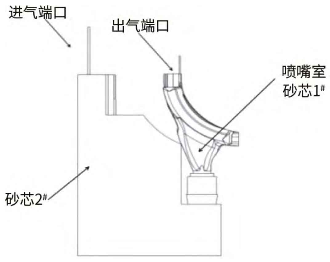
Add to the sand core in the nozzle chamber ϕ 25mm through-hole steel pipe. Before pouring, sand casting manufacturers inject compressed air into the steel pipe to reduce the temperature of the sand core in the nozzle chamber. Injecting compressed air requires an intake port and an exhaust port, but due to a reinforcing rib in the middle of the nozzle chamber, it creates an obstacle for introducing compressed air. The through-hole steel pipe is not allowed to pass through the rib plate to connect the two ends of the nozzle chamber sand core as the inlet and exhaust ports. Therefore, a special 2 # sand core is set up outside the nozzle chamber, and added to the 2 # sand core ϕ A 25mm through-hole steel pipe serves as the intake port for compressed air, and is added to the sand core of nozzle chamber 1 # ϕ A 20mm through-hole steel pipe serves as the exhaust port.
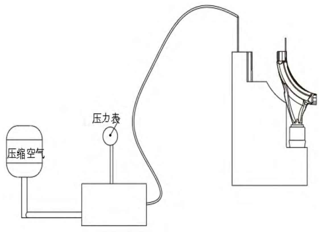
Before pouring the steel liquid, compressed air is introduced, and the working diagram of the air cooling system is shown in Figure 5.
3. Production validation and effectiveness
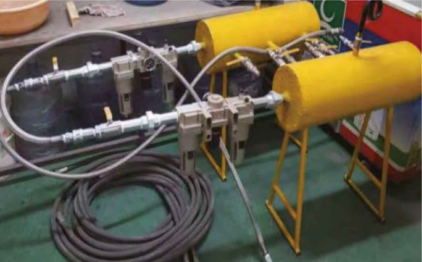
In the actual production process of sand casting manufacturers, the compressed air cooling system is shown in Figure 6. The opening time of the air-cooled pipe is 180 seconds, the temperature at the inlet end is room temperature of 20 ℃, and the outlet temperature is 60 ℃. Maintaining a temperature difference of more than 40 ℃ between the outlet and inlet achieved the effect of cooling the sand core temperature in the nozzle chamber.
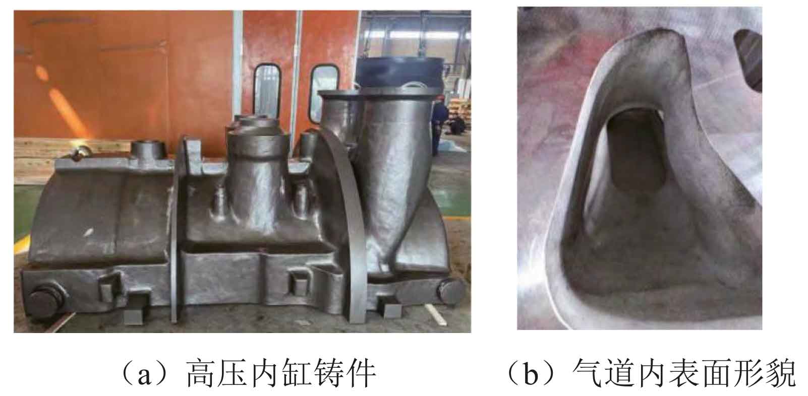
The high-pressure inner cylinder produced by sand casting manufacturers is shown in Figure 7 (a), and the surface quality of the airway is shown in Figure 7 (b). From the figure, it can be seen that there is no sand sticking at the nozzle chamber, making cleaning convenient; The internal quality of the casting is good without excessive shrinkage or porosity defects, and it is qualified through one ultrasonic inspection.
4. Conclusion
The use of an air cooling system avoids prolonged high-temperature burning and erosion of the sand core, while also giving it good collapsibility. The sand core does not exhibit sintering, and sand casting manufacturers completely solve the problem of sand sticking in narrow air passages of steel castings, improving the quality of the inner wall of the air passage. In practical operation, the following points need to be noted:
(1) Sand casting manufacturers design steel pipe dimensions and compressed air related process parameters reasonably based on the structural characteristics and technical requirements of steel castings.
(2) Sand casting manufacturers need to turn on compressed air before pouring to ensure that the temperature difference between the compressed air at the inlet and outlet is more than 40 ℃, ensuring cooling effectiveness.