1. 3D model of box
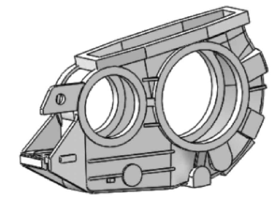
The three-dimensional model of the box is shown in Figure 1. The material of the box is ALSi7Mg0.3, and the outline dimension is 1003mm × 220mm × 608mm, the maximum wall thickness is 40mm, the minimum wall thickness is 5mm, and the maximum aperture is Φ 350mm, minimum hole diameter Φ 10mm, mass 56.6kg, uniform wall thickness, and small batch production. The overall structure of the box is relatively symmetrical, the internal cavity structure is complex, and there are many bosses and rib plates outside. Sand casting is adopted, and the minimum casting hole is Φ 20mm。
2. Sand casting process scheme
Sand casting and manual molding are adopted. In order to obtain high strength sand mold and sand core, resin binder, self hardening resin sand and core box are used to make the core manually.
3. Selection of parting surface
Two parting schemes are designed, as shown in Figure 2. The parting surface of scheme 1 is selected at the maximum section of the sand casting, the sand box will not be too high, and the parting surface is flat, which is convenient for core removal, but it is not conducive to the mold taking of the flange on both sides of the sand casting, so it needs to be made into an EPC. In scheme 2, the parting surface ensures that the large plane is under and the number of sand cores is small; However, the sand box is high, the modeling is difficult, and it is inconvenient to fill sand, compact and lift the mold. Considering comprehensively, scheme 1 is selected in order to reduce the number of sand cores, facilitate core setting and reduce process difficulty.
4. Design of gating system
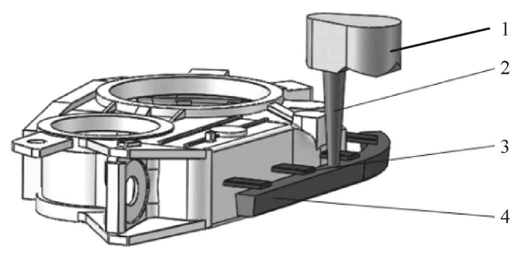
During aluminum alloy melting, the alloy liquid cools down quickly and is easy to oxidize and inhale. Moreover, the solidification shrinkage of aluminum alloy is relatively large, which is easy to produce shrinkage cavity and porosity. The open gating system is adopted for sand castings, and the side injection gating system is adopted for the convenience of mold lifting, and the sprue is set on the parting surface. The schematic diagram of the gating system is shown in Figure 3.
The transverse sprue and inner sprue of aluminum alloy sand casting are set in the upper sand box. An extension section is set at the end of the transverse sprue so that the metal liquid entering the mold cavity can flow smoothly to ensure the integrity of mold filling of sand castings. The internal sprue is flat, which can not only block slag, but also adopt four evenly distributed internal sprues, which is conducive to adjusting the temperature distribution of metal liquid and making the sand castings solidify in sequence. At the same time, the position of the sprue cup must be high enough to ensure that sufficient pressure can be provided to hydraulically press the metal into the mold.
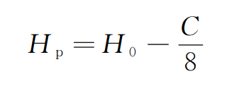
Aluminum alloy sand castings adopt side injection gating system, and its average static pressure head is:
Where HP is the minimum average static head required for sand casting, mm; H0 is the distance from the top of the sprue cup to the runner, mm; C is the height of the mold, mm. According to the formula, the average static head of sand casting is 130mm and the total static head is 260mm.
The mass of aluminum alloy sand casting is 56.6kg and the mass of gating system is about 15kg, so the pouring mass of aluminum alloy sand casting is about 71kg. According to the pouring quality, the cross-sectional area of the sprue shall be 1000mm2 and the diameter shall be Φ 25mm。 According to the determination, the section ratio of each sprue is Σ a straight: Σ a cross: Σ a inner = 1:2:2, so it is calculated that the area of the cross sprue and the area of the inner sprue are 2000mm2. The number of ingates is set as 4, and the cross-sectional area of each ingate is 500mm2.


