
1. Overview of parts of four-way elbow valve box
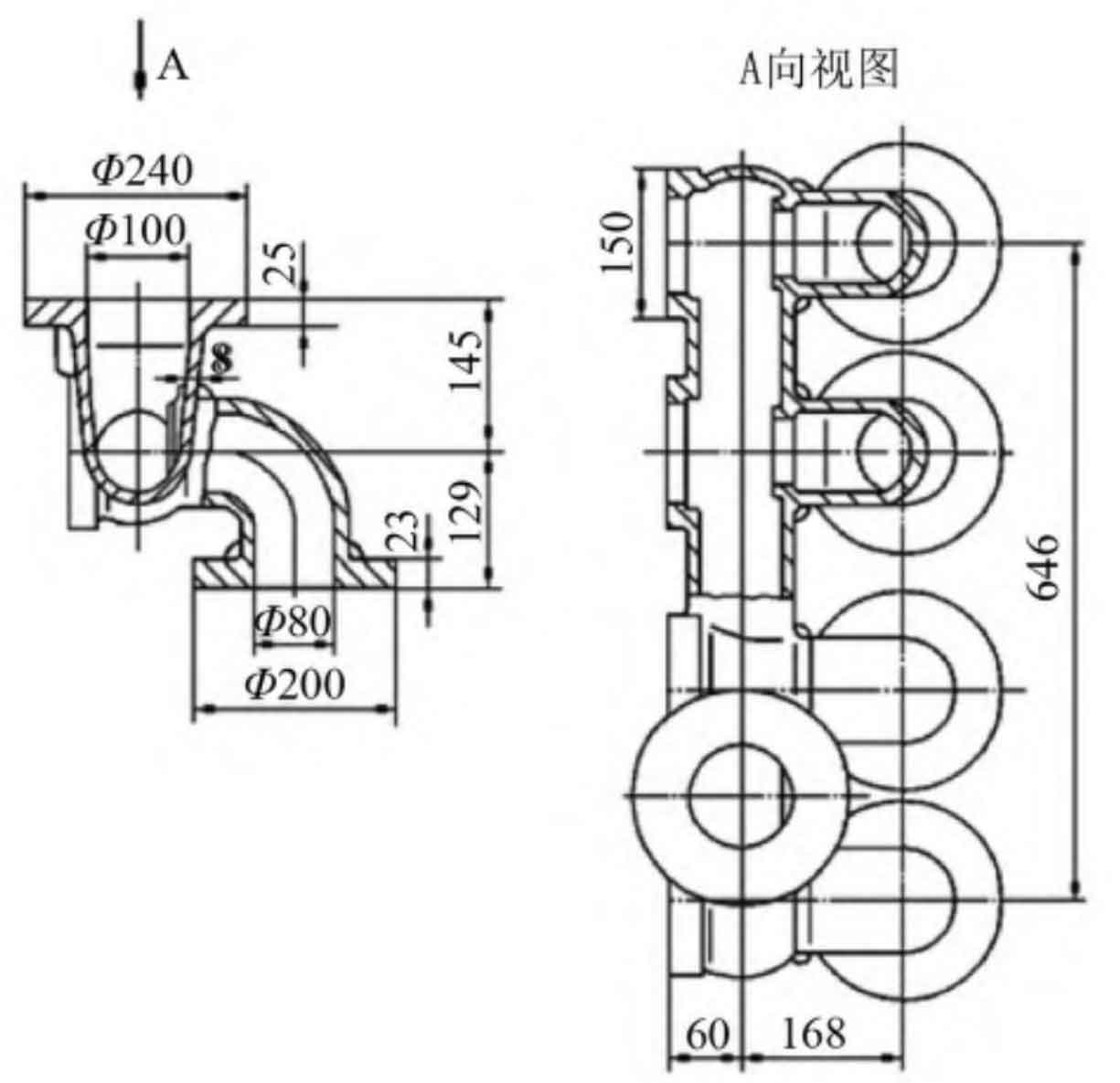
The silicon brass four-way elbow valve box is a ten-way structure, and the part size diagram is shown in Figure 1. After placing 4 mm machining allowance on the machining surface, the length is 846 mm, the width is 328 mm, the height is 274 mm, and the maximum diameter is Ф 100 mm with a minimum wall thickness of 8 mm. There are 10 flanges: 2 round flanges on the top of the valve box( Ф 240 mm 25 mm), 4 round flanges under the elbow( Ф 200 mm 23 mm), 4 flanges (150 mm 150 mm). This valve box requires that the valve box and the valve cover be together for tightness test with 4.5 MPa hydraulic pressure. Due to the large surface area of the four-way elbow valve box, the probability of leakage in the hydraulic test is high.
2. Determination of overall sand casting process plan
(1) Determination of pouring position. The structure of the four-way elbow valve box is relatively complex. First of all, the pouring position should be determined. On the one hand, the factors of convenient mold lifting should be considered, and on the other hand, the factors of riser feeding should be considered. Generally, the horizontal parting is carried out in the middle of the valve box so that the main part of the valve box can be easily lifted.
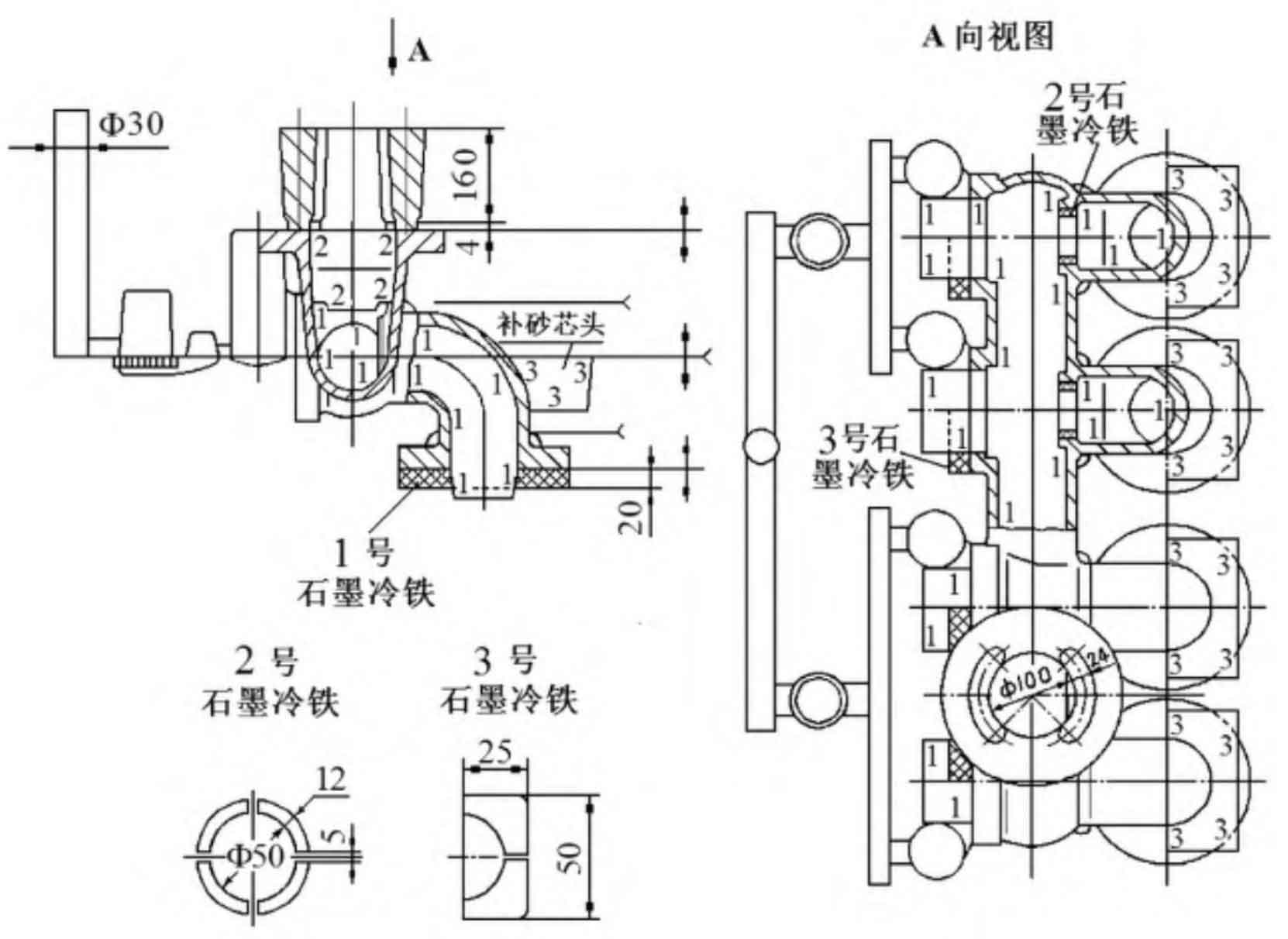
(2) Setting of sand core. Since the sand core under the round flange at the top of the valve box is connected with the main sand core, it is not convenient to lower the core during modeling, so the sand core in the chamber is divided into 1 # main sand core (1) and 2 # sand core (4). The upper and lower round flanges on the outer mold shall be removed to facilitate mold lifting; In addition, there will be obstacles when placing sand cores at the elbow of the valve box, so 4 sand core heads of No. 3 shall be set. It can also be seen from the structure of the four-way bend valve box that because both ends of the valve box are closed in the length direction, it can not be supported and positioned by the core heads at both ends. It can only be supported and positioned by the core head under the bend and the core head at the flange, which is difficult to process.
(3) Determination of molding sand process. Considering that the material of the four-way elbow valve box is silicon brass ZCuZn16Si4, and the requirements of hydraulic test are high, in order to make the appearance of the sand casting of the valve box have a certain chilling effect, the green sand is used as the molding sand, which can also make the appearance of the sand casting more smooth and clean. Considering the complex structure of sand core and the requirement of high strength to facilitate core laying, clay sand dry mold sand core is adopted. That is, the molding sand process is green sand and dry core. See Figure 2 for the process plan.
3. Setting of pouring system
Two waist circular risers (160 mm high) are set on the two circular flanges on the top of the four-way elbow valve box for feeding, and a blind riser is set on one side of the flange( Ф 70 mm × 150 mm).
Due to the long size of the four-way elbow valve box in the length direction, the transverse runner is divided into two parts, and the alloy liquid passes through Ф The 36mm sprue enters the first runner and then passes through the sand filter screen( Ф 5 mm × 27 mm hole) enters the second transverse runner, and then enters the concealed riser to pour sand casting. After the alloy liquid passes through two layers of runner and sand filter screen, it can effectively avoid the sand mold casting defects of oxidation inclusion.
4. Setting of cold iron
Setting of graphite chill: ① Set 1 # graphite chill (8 pieces in total, 1/2 round, 20 mm thick) on the bottom surface of the square and round flange under the elbow for chilling; ② Set No. 2 graphite chill iron (16 pieces in total, 1/4 circle, 8 mm thick) at the four round holes at the horizontal position in the valve box chamber for chilling; ③ 3 # graphite chill iron (8 pieces in total, 12 mm thick) is set outside the method flange for chilling (Fig. 2). Under wet type conditions, a thin layer of oil is applied to the working surface of graphite chill before box closing to prevent moisture absorption of graphite chill.
5. Other process points
The dimension of the outer mold of the elbow valve box shall be subject to negative tolerance (for submersibles, parts have strict quality requirements to avoid overweight). Machining allowance: except for the upper and lower flange faces, which are 4 mm, the other flange faces and the inner cavity with graphite chill are 3 mm. The external mold shrinkage is 1.5%, and the core box shrinkage is 0.8%.
6. Key points for operation of four-way elbow valve box
When lowering the sand core, wrap the No. 1 sand core horizontally with a cloth and drop it steadily. Pay attention to whether the core head of the elbow sand core is fully seated. Observe whether the water path between the 1 # sand core and the mold cavity (i.e. the wall thickness of the sand mold casting after solidification) is uniform, then lower the 3 # sand core head, and pay attention to whether the water path between the 1 # sand core and the 3 # sand core is uniform. When testing the cover box, check the wall thickness above the 1 # sand core arc surface with a clay bar, and it must be adjusted to meet the requirements. When the No. 2 sand core head is lowered onto the No. 1 sand core, it should also be aligned according to the size of the surrounding cavity, and then press a small section of mud strip on the top of the No. 2 sand core, and then cover the box, and compact the mud strip so that the No. 2 sand core does not float or move. In addition, the air outlet rope is buried in the core bone of No. 1 sand core, and the air outlet rope is pulled out to form the exhaust channel of No. 1 sand core when lowering the core, so as to facilitate the gas from No. 1 sand core to be discharged from the mold smoothly during pouring.
The pouring temperature is 1000~1040 ℃. The sand casting mass of the four-way elbow valve box is 75 kg, the pouring system mass is 60 kg, the pouring mass is 135 kg, and the process yield is 55.5%.