
Although diesel engines have issues such as emission pollution and high noise, they are still an important choice for the power of mobile vehicle equipment. Diesel engines have high torque, good economic performance, and wide applications. With the acceleration of industrialization in recent years, high efficiency and light weight requirements have been put forward for engines. High end high-power diesel engines, due to their high requirements for wall thickness, geometric dimensions, weight, and structure, are prone to defects such as porosity, inclusions, cold shuts, shrinkage, and dimensional deviations during the sand casting process. This not only increases production costs but also causes resource waste, seriously restricting the development of the diesel engine industry.
1. Technical indicators and quality requirements
The material of the cylinder body of a high-power diesel engine of a certain model is HT300, and the maximum weight of the sand casting is 720 kg. The maximum contour size of the diesel engine cylinder body is 1650mm x 700 mm x 500 mm. There are a total of 8-20 cylinder holes in the diesel engine cylinder body, and the wall thickness difference of the sand casting is large, with a maximum wall thickness of 75.13 mm and a minimum wall thickness of 8 mm. Easy to produce defects such as shrinkage, porosity, and cold shut. The mechanical properties require a tensile strength of ≥ 276 MPa and a hardness of 179-255 HBW for the body; Metallographic requirements include A type graphite ≥ 80%, B type graphite ≤ 10%, D type graphite+E type graphite ≤ 10%, pearlite content ≥ 95%, ferrite content ≤ 5%, total carbide content ≤ 5%, and graphite size grades 2 to 6.
After the sand casting of the diesel engine cylinder block is completed, it is necessary to visually inspect the inner cavity of the diesel engine cylinder block, and use MT flaw detection to inspect the outer surface. No cracks are allowed. And conduct a 1.5 MPa water pressure test after processing, maintain the pressure for 30 minutes, and ensure that the sand casting has no water seepage or leakage.
2. Sand casting process
2.1 Melting and pouring process
Considering the small minimum wall thickness of the diesel engine cylinder block, the melting process adopts high carbon equivalent and low alloying raw iron liquid, and strictly controls harmful trace elements. The furnace material ratio is 60%~70% scrap steel and 40%~30% return material. The final chemical composition of the iron liquid is shown in Table 1.
| C | Si | Mn | P | S | Cu | Cr | Ti |
| 3.15 | 1.80~1.90 | 0.70~0.80 | <0.05 | <0.1 | 0.85 | 0.25~0.28 | <0.025 |
Inoculation treatment should be carried out before pouring the molten iron. Good inoculation treatment can increase the fluidity of the molten iron, increase the number of eutectic clusters, reduce the tendency of white spots, shrinkage rate, and residual stress. The temperature of the molten iron being discharged from the furnace is controlled at 1420 ℃± 10 ℃, and flow inoculation is adopted. The pouring temperature is controlled at 1370 ℃± 10 ℃, and the pouring time is 25-30 seconds. Three pieces are poured in one package, which can avoid defects such as cold shuts and air holes caused by the decrease in molten iron quality and large pouring temperature difference.
2.2 Styling process
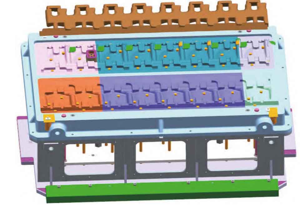
Based on the sand casting process habits of the enterprise, a process plan has been developed as shown in Figure 1.
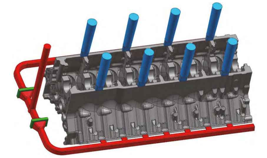
According to the structural characteristics of the diesel engine cylinder block, the sand casting process selects a V-shaped large cross-section parting surface, and the outer and inner sand cores are made of furan resin sand. Due to the complex internal structure of the sand casting, multiple complex sand cores need to be designed to form the inner cavity structure, especially the U-shaped water channel core and the tappet core. To prevent sand sticking from causing difficulties in cleaning the subsequent process, zirconium based high-strength anti sand sticking coating is selected as the coating.
Due to the large contour size of the engine cylinder block, there are significant differences in the three-dimensional dimensions in various directions. Based on the differences in three-dimensional dimensions and wall thickness, different sand casting shrinkage rates of 0.91%, 0.85%, and 0.85% are used in the length, width, and height directions, respectively.
The pouring system adopts a U-shaped semi enclosed pouring system, and the ratio of the cross-sectional areas of each component is ∑ S straight: ∑ S horizontal: ∑ S inner=1:1.65:1.34. A filter device is installed in the transverse pouring channel, with a specification of 120 mm x 75 mm x 20 PPI, totaling 2 pieces, to improve the purity of the iron liquid, reduce slag inclusion defects in sand castings, and slow down the flow rate of the iron liquid to prevent the sand core in the inner cavity of the sand casting from being washed away by too fast inflow speed.
The sand mold combination first inserts a single inner cavity main core and end face core into the inner cavity, checks the verticality and cylinder size of each main core, and after confirming the size is correct, uses long bolts to tighten and lock all main cores. The sand box design adopts three types of boxes: bottom, middle, and cover. After the core is assembled, a middle box is placed on the assembled sand core, and resin sand is filled around it for solidification. The sand mold is sealed with a sealing mud strip, and the cover box is closed for pouring.
3. Trial production of sand castings
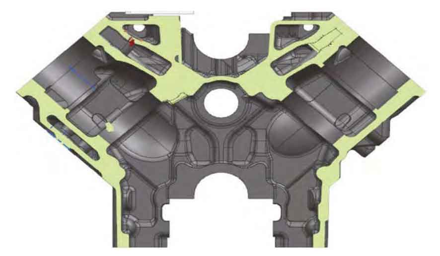
Small and large-scale production was carried out according to the above process, and the main defects were porosity, sand inclusion, and leakage. As shown in Table 2, the leakage rate of diesel engine cylinder bodies accounts for more than 50% of the entire scrap rate. The leaking diesel engine cylinder bodies cannot be repaired and are scrapped. Upon inspection of the product, it was found that the leakage was located at the junction of the water channels and tappets in each cylinder of the diesel engine block, as shown in Figure 2. The wall thickness at this location was only 8 mm.
| Production frequency | Input/piece | Scrap/piece | Scrap rate (%) | Leakage/piece | Sanding/piece | Pores/piece | Inclusion/piece | Other/piece |
| First production | 42 | 18 | 42.9 | 9 | 3 | 2 | 4 | 1 |
| Second production | 116 | 47 | 40.5 | 21 | 5 | 8 | 11 | 2 |
| Third production | 131 | 27 | 20.6 | 13 | 3 | 4 | 5 | 2 |
4. Defect analysis and judgment
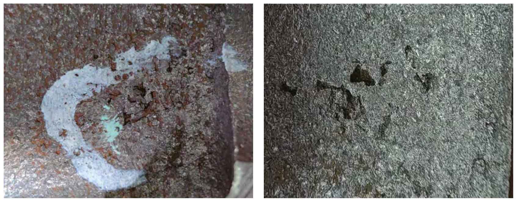
Anatomy of the leakage location, as shown in Figure 3, reveals a large number of pores and inclusions visible to the naked eye. The inner walls of the pores exhibit irregular oxidation patterns, some of which are relatively smooth. For this purpose, further analysis was conducted using metallographic microscopy, SEM, and EDS.
4.1 Metallographic analysis
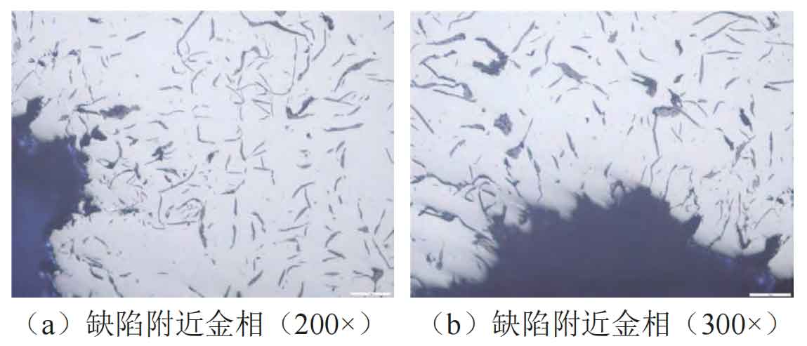
The metallographic structure was observed using a metallographic microscope, and the obtained metallographic structure is shown in Figure 4. From Figure 4 (a), it can be seen that the matrix structure far from the defect location is ferrite and pearlite, and the graphite distribution shape is composed of A-type graphite and a small amount of C-type graphite. Continuing to enlarge the defect location to (b), it can be seen that there are thick and irregular block shaped graphite around the defect, which has a certain degree of variability. Based on metallography and defect analysis, the fundamental reason affecting its formation is that the wall thickness at the defect site is relatively thin, and some inclusions intensify the cooling rate. The uncontrolled growth of graphite leads to a longer length and a coarser morphology.
4.2 SEM and EDS analysis
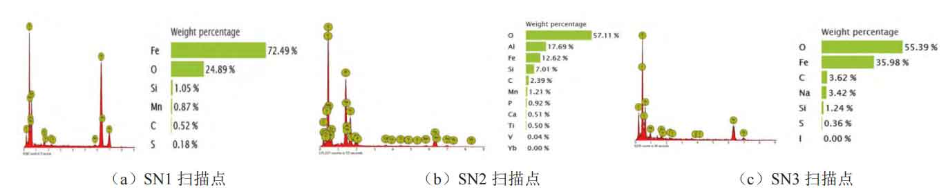
By dissecting the leakage location of sand castings and extracting three samples with different cylinder holes of the same sand casting, numbered SN1, SN2, and SN3, the surface of the samples was cleaned and dried. SEM and EDS were used to analyze the samples, observe the morphology characteristics of defects, and determine the proportion of chemical elements.
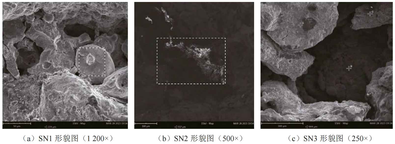
From the morphology and energy spectrum analysis in Figures 5 and 6, it can be observed that there are many impurities present in the pores of SN1, SN2, and SN3 samples. The chemical composition analysis of the energy spectrum shows that there are elements such as Al, Na, Ca, Si, Mn, etc. in the pores, which combine with oxygen to form oxides, all of which may form “slag pores” defects.
4.3 Numerical simulation analysis
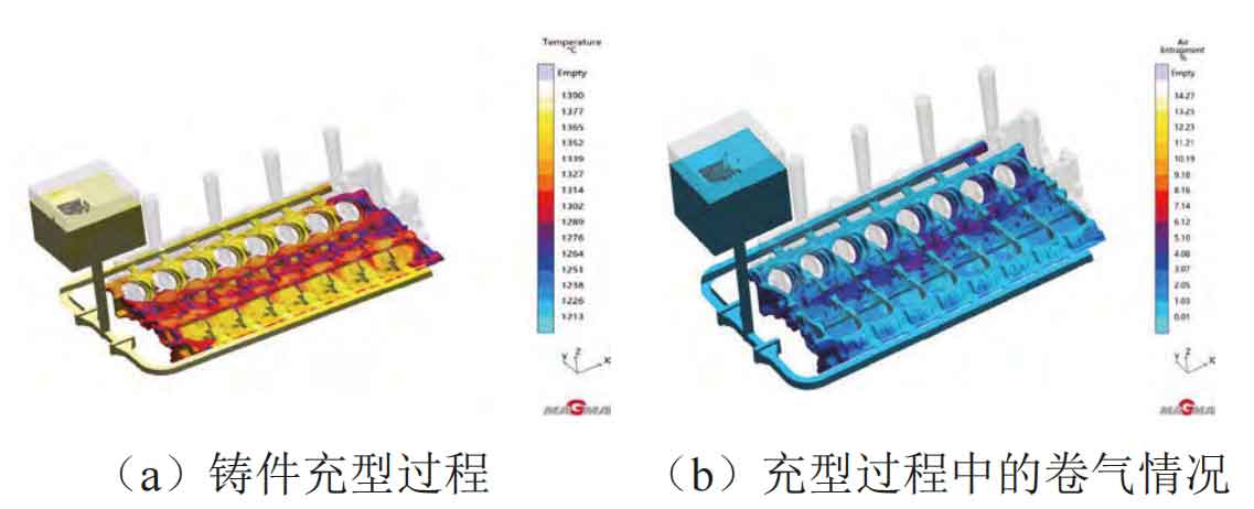
To further determine the defects in the diesel engine cylinder block, MAGMA was used for numerical simulation. The sand core, mold, pouring system, gate, etc. were imported into MAGMA, and the material categories were defined. The Decal grid was divided, and the parameters were determined. Real time gas generation defect risk of the sand mold and core on the sand mold casting, gas particle tracking of the sand core gas generation, filling temperature and gas entrapment during the pouring process of the sand mold casting were simulated and calculated for filling and solidification, As shown in Figures 7 and 8.
From Figure 7, it can be seen that as the molten iron enters the inner gate and rises with the liquid level, a large amount of gas and gas particles are generated in the U-shaped waterway core and tappet core when they are wrapped by the molten iron. These gases come from two aspects: the first is the gas generation of the sand core itself; The second is the gas produced by excessive oxidizing substances. From Figure 8, it can be seen that when the molten iron enters this area, a low-temperature zone appears, and from the perspective of gas entrapment, the amount of gas entrapment is also the highest. Analysis suggests that a large amount of binders and other auxiliary materials are used during core assembly in this area. When the molten iron enters this area, it quickly dissociates the binders and oxidizes, and a supercooled zone appears at this location with a temperature close to the solidus temperature.
In summary, after various detection methods and software judgments, it is highly likely that this defect belongs to the category of slag inclusion and porosity defects. In addition, the coarse and thin structure has led to a high proportion of leakage defects in the casting. Through analysis, it is found that during the core assembly process, after the U-shaped water channel core, tappet core, end face water channel core and other sand cores are segmented, a large amount of core adhesive is needed to fix them. However, when the core adhesive is tested at 850 ℃, its gas generation rate is as high as 162 mL/g and the gas generation speed is slow. When the iron liquid is in the solid phase zone or below the solid phase temperature, the gas cannot be discharged in time, resulting in pores. Secondly, the coating used is an alcohol based alkaline coating. Upon inspection, it was found that the main component of the coating is mullite (aluminum vanadium earth) aluminum silicate mineral, which contains a large amount of Al2O3 and a small amount of Na based substances. After heating, these substances mix and decompose with oxygen, forming slag pores. Finally, diesel engine cylinder blocks require high strength and thin wall thickness. A large proportion of scrap steel and carburizing agents are used for ingredient melting, and these materials also contain elements such as Al, N, and Ti that affect cast iron to varying degrees. While forming pores, they can also cause shrinkage defects, which affect the density of sand castings.
5. Improvement measures and verification effects
5.1 Improvement measures
(1) Changing the core assembly method of sand cores: By optimizing the process and producing corresponding process equipment, the main core and end face core are combined outside the mold to avoid sand inclusion defects caused by the combination inside the mold. Design specialized core assembly and lower core tooling, pre assemble the sand core outside the mold, inspect and measure its size to be qualified, lock it with bolts and fix it, blow off loose sand, and lower the entire core tooling into the mold cavity.
(2) Use mixed coatings or graphite based coatings instead of alkaline coatings to reduce the generation of pores and slag holes. The existing coatings are alkaline coatings, with the main component being mullite, which contains a large amount of Al, Na and other components. Through performance tests such as anti sand adhesion of the coatings, it has been decided to use alcohol based 7804 coatings for brushing or flow coating. The basic aggregate of this coating is phosphorus flake graphite, which effectively prevents the occurrence of problems such as pores, oxides, and sand adhesion. The operating process is to brush twice, control its Baume value to 45 Be ° for the first time, and place it for 10 minutes without ignition, Adjust the Baume value to 60-65 Be ° and use natural gas to quickly bake to a dry state.
(3) For sand cores such as U-shaped waterway cores and tappet cores, the cold core box cutting method is adopted to replace the original manual furan resin sand process, improving the strength of the sand core while reducing the occurrence of defects such as sand holes. The U-shaped waterway core, tappet core, etc. are designed as cold core box cores, as shown in Figure 9. The basic length is mainly based on the cylinder body of a certain Type 8 diesel engine, and the length of the sand core is increased according to different models. After changing to a cold core box, the size and strength of the sand core are improved.
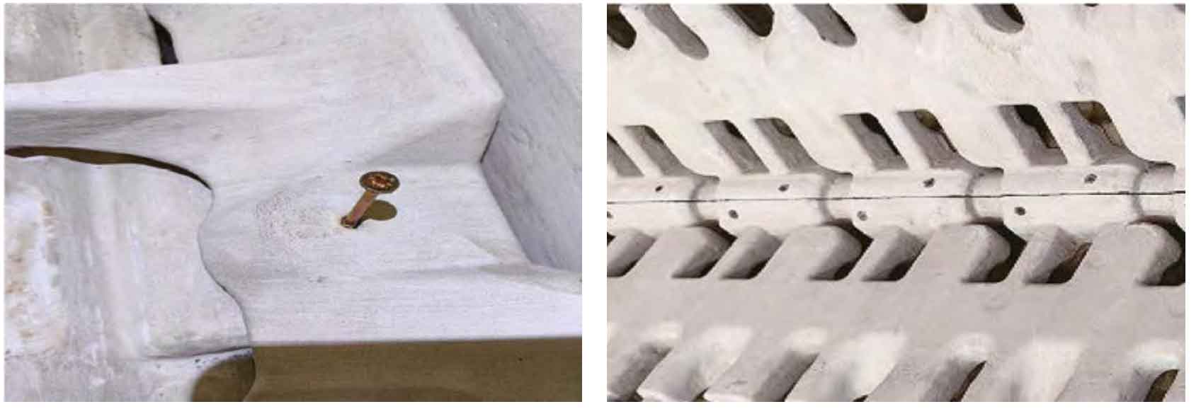
(4) Changing the method of using a large amount of adhesive in the original cavity core assembly to iron nails effectively avoids the occurrence of porosity defects caused by prolonged gas release from the adhesive core. When assembling sand cores such as waterway cores and tappet cores using the original process, a large amount of core adhesive was needed to bond and fix the joint positions of each core. Now, it is replaced with self tapping screws, effectively avoiding the occurrence of porosity defects caused by long-term gas release of the core adhesive, as shown in Figure 10.
(5) Adjust the smelting process ratio, add high-temperature graphitization carburizing agents, inoculants, etc. to obtain sand castings with dense structure, and adopt high-temperature purification of molten iron before discharge to improve the purity of sand castings. Due to the use of a large proportion of scrap steel added back to the furnace for melting in the original process, the amount of carburizing agent used also increases with the increase of scrap steel, resulting in a significant increase in its nitrogen content. Nitrogen promotes the formation of carbides and affects graphite growth, leading to the formation of pearlite, shortening and bending of graphite ascending order, and further passivation of the entire end of the flake graphite. To improve this issue, the original process plan was optimized. To avoid the genetic impact of the original return material on the molten iron, a batching method of 10%~15% pig iron and 90%~85% scrap steel was adopted, and the use of return material was cancelled. Finally, the composition of the molten iron was adjusted as shown in Table 3.
| Composition | C | Si | Mn | P | S | Mo | Cu | Ti | Al |
| Original liquid iron | 3.25 | 1.48 | 0.53 | 0.022 | 0.095 | 0.024 | 0.68 | 0.0093 | 0.010 |
| Final molten iron | 3.30 | 1.88 | 0.74 | 0.023 | 0.093 | 0.28 | 0.67 | 0.011 | 0.008 |
When the molten iron melts to 1400 ℃, take a spectral sample and adjust its composition according to the above table. Reheat and raise the temperature to 1520 ℃ for 5-10 minutes of overheating and standing. Further increase the overheating temperature, the nucleation ability of the molten iron will decrease, the graphite morphology will deteriorate, and even free carbides will appear. When the furnace is produced, a flow inoculation method is used to inject 8-24mm granular silicon barium inoculant into the ladle. The essence of inoculation is to use the inoculant to affect the eutectic reaction of the molten iron. Good inoculation treatment is the basic guarantee for gray cast iron to obtain small and uniform A-type graphite, eliminate carbides and undercooled structure, reduce section sensitivity and hardness dispersion, and improve the mechanical and processing properties of the casting.
5.2 Verification effect
Through the above process improvements, quality inspection was carried out on the diesel engine cylinder block. In terms of production quality, sand castings were produced using a method of 4 pieces+8 pieces+16 pieces, and the defect areas were dissected and processed for verification. At the original location of leakage defects, the organization was dense, and no defects such as sand inclusion, slag inclusion, and porosity affecting the performance of sand castings have been found. The final product quality performance is shown in Table 4:
| Batch | Input/piece | Scrap/piece | Scrap rate (%) | Leakage/piece | Sanding/piece | Pores/piece | Inclusion/piece | Other/piece |
| First batch | 4 | 0 | 0 | 0 | 0 | 0 | 0 | 0 |
| Second batch | 8 | 0 | 0 | 0 | 0 | 0 | 0 | 0 |
| Third batch | 16 | 1 | 6.25 | 0 | 0 | 1 | 0 | 0 |
| Fourth batch | 73 | 3 | 4.51 | 1 | 0 | 1 | 0 | 1 |
6. Conclusion
After optimizing the process and taking measures, the leakage rate of the high-power engine cylinder block was reduced to below 2%, resulting in a significant reduction in defects such as sand inclusion, slag inclusion, and porosity in sand castings. The comprehensive scrap rate was controlled at 4% to 6%, basically meeting the quality improvement target requirements. In summary, the improvement experience can be summarized as follows:
(1) In process design, it is necessary to fully analyze and consider the deformation, fracture, and operability of the sand core, and make use of factory resources as much as possible to use equipment such as cold core boxes to make cores without improving the strength of the sand core and reducing sand inclusion defects.
(2) The elements such as Al and Na in the coating will increase the gas generation of the sand core, react with oxygen to form oxide inclusions, and cause the formation of slag pores in local locations of sand castings.
(3) In terms of core assembly, the gas generation of the binder is relatively large, which affects the flow of molten iron and even causes the generation of oxidation slag inclusions in sand castings. By improving the use of self tapping screws to fix the sand core, the gas generation inside the mold can be reduced.
(4) Design a dedicated lower core fixture and use the method of outer core assembly to lower the core, which can effectively reduce the risk of sand inclusion in sand castings.
(5) When producing high-strength sand castings, avoid a large proportion of scrap steel ingredients, add 10%~15% pig iron to reduce the generation of nitrogen content in the molten iron, and use high-temperature graphitization carburizing agents and inoculants to obtain denser sand castings. The molten iron is also left to stand at high temperature to improve its purity.