In the process of aircraft engine development, it is necessary to systematically detect the flow rate, flow rate, pressure, and temperature of combustion gases (high temperature, high pressure, high flow rate) under different working conditions. Therefore, the inner chamber of its jet detection device is usually manufactured into a complex streamline structure, with a shape like a volute, and equipped with specialized high-precision detection equipment. The stainless steel volute components in this device require integral casting, and due to the need to withstand high-temperature gas erosion for a long time, cracks, pores, shrinkage holes, slag inclusions and other defects are not allowed to appear inside the casting. To ensure the performance requirements of the snail shell, our company adopts the Baozhu sand alkali phenolic resin casting process for the production of casting blanks. Alkaline phenolic resin combined with spherical pearl sand has high fire resistance and can increase the high-temperature yielding of the sand mold, which has a good effect on reducing casting cracks, improving the dimensional accuracy and surface quality of castings.
1. Product Introduction
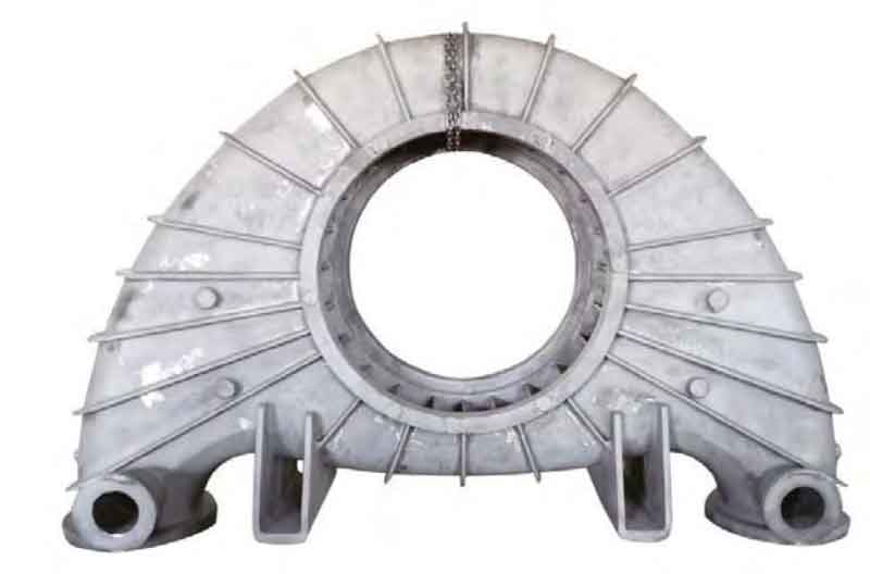
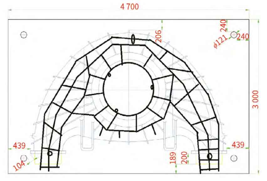
The material of the stainless steel volute is ZG12Cr18Ni9Ti, and the composition control is shown in Table 1. The single weight of the casting is 3.2 tons, with a maximum size of 3800 mm and a wall thickness of 20 mm. It belongs to a typical thin-walled structural component, as shown in Figure 1. There are 30 partitions distributed in the volute cavity, with a wall thickness of 20 mm and a height of 200 mm. The partitions are connected to the upper and lower end faces to form a hot spot. Based on the above characteristics, the snail shell component with a complex structure and uneven wall thickness is prone to deformation and casting defects when cast as a whole. This requires that in the design of the casting process plan, attention should not only be paid to the shrinkage of the hot spot area, but also to smooth mold filling, slag removal, and gas removal.
2. Introduction to production process
2.1 Mold Plan
Based on the symmetrical upper and lower structure of the casting, local excess control valve flanges, and installation protrusions, the above parts are made into active blocks in the mold design. The same wooden model board can complete the shape of the upper and lower sand boxes. The sand mold is positioned with a steel cone, with a negative division of 3mm. The overall shrinkage rate of the steel liquid is designed to be 2.5%, with a shrinkage rate of 1.0% for the inlet and outlet flanges of the volute and a machining allowance of 15mm. The quality of the sand core is estimated to be about 3 tons based on the density of Baozhu sand of 2.0 g/cm3. If it is difficult to make a whole sand core, it is changed to 1/2 sand core. The symmetrical center plane of the upper and lower parts is used as the parting surface, and sawdust and grass rope are added in the middle to increase the yield. In addition, due to the large span size of the sand core, in order to prevent deformation and drift during the pouring process, a core bone structure reinforced by steel reinforcement welding was designed, as shown in Figure 2.
2.2 Casting process
2.2.1 Process sprue design
In order to shorten the pouring and filling time, reduce defects such as slag and holes in large thin-walled castings, the process runner is designed according to the double ladle pouring method. At the same time, to prevent sand from entering the castings during pouring, ceramic pipes are used to arrange the runner, which is also conducive to the flow of steel and the filling of castings, avoiding inclusions and defects. As shown in Figures 3 and 4, 6 risers are evenly distributed on the flange, and subsidy risers are arranged on the inlet and outlet flanges. Air release rods are arranged at the high points of the upper box outer shape, and the cast test rods are designed on the inner runners on both sides of the parting surface. Considering the large volume shrinkage of the steel liquid, an open pouring system is adopted for casting pouring, and the cross-sectional ratio of each unit is about ∑ S straight: ∑ S horizontal: ∑ S inner=2:3:4. Two schemes are designed for the layout of the transverse and inner runners.
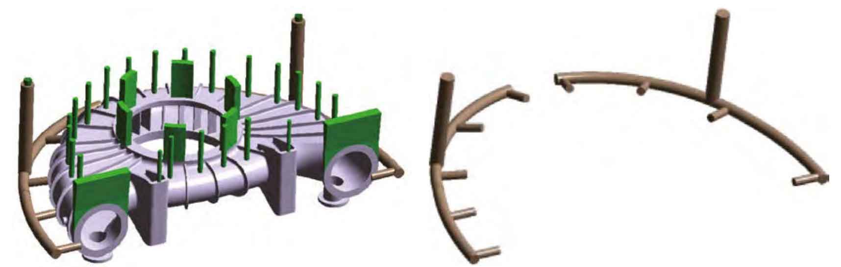
(1) Plan 1: The production rate of the process is 63.33%. A layer of inner runner is arranged on the parting surface, and the transverse runner and inner runner are respectively used ϕ 120 mm and ϕ 90 mm ceramic tube, as shown in Figure 3.
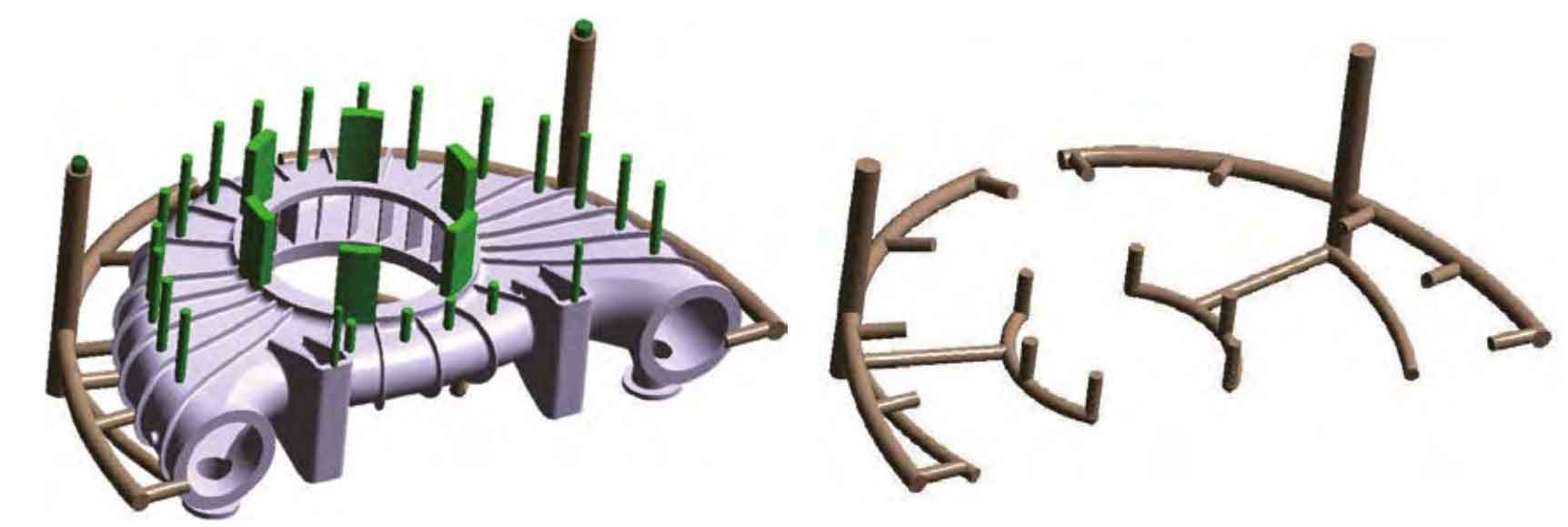
(2) Plan 2 has a production rate of 60.24%. Based on Plan 1, an inner runner is added at 1/2 of the lower box cavity to form two stepped inner runners. This ensures good filling and reduces the temperature difference at the bottom, as shown in Figure 4.
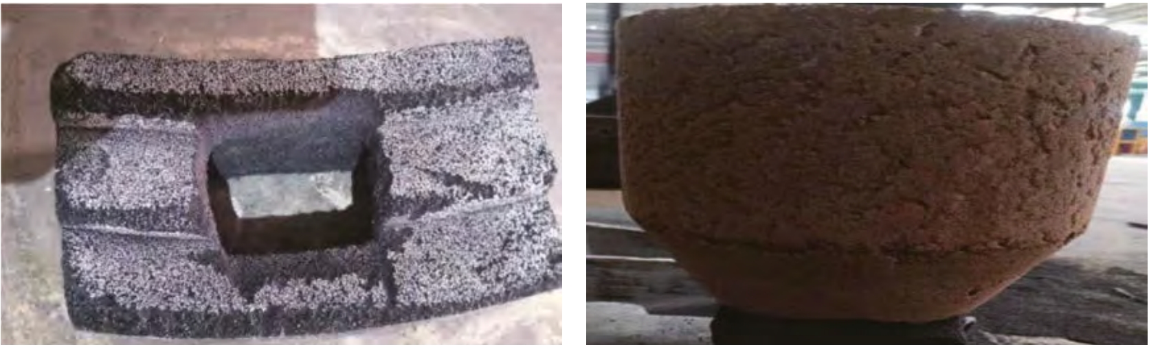
(3) To improve the yield of castings, an easy to cut riser seat was adopted, as shown in Figure 5. Mix 80% pearl sand, 15% resin, 4% curing agent, and waste steel balls( ϕ ≤ Mix 0.1 mm) 1% and place the mixed sand in a self-made mold for 5-10 minutes for hardening and shaping; When the burial height of the sand is the same as the height of the easy to cut riser, connect the position of the liquid inlet at the bottom of the heating insulation riser with the position of the top of the set sand mold easy to cut riser seat. By using this method, while improving the yield of castings, the cutting time for each riser can be reduced from 5 minutes to 1 minute.
2.2.2 Process simulation analysis and optimization design
Set parameters according to the actual pouring process in CAE software, where resin sand is used as the casting material, the heat transfer coefficient between the casting and the sand box is 700 W/(m2 · K), the pouring temperature is set to 1600 ℃, the initial sand mold temperature is 20 ℃, the pouring time is 93 seconds, the heat transfer method is air cooling, the external heat transfer conditions are convection and radiation, and the permeability of the sand mold is considered. Other parameters are selected by default from the software.
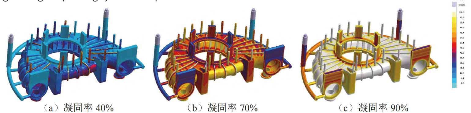
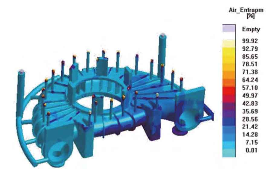
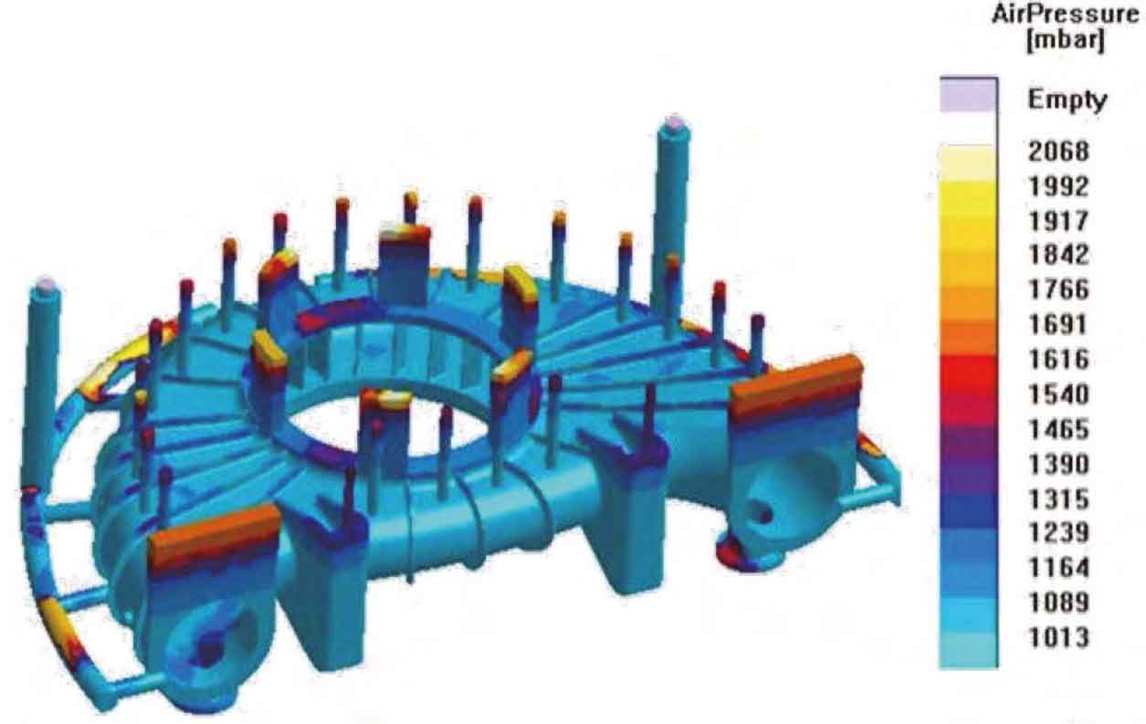
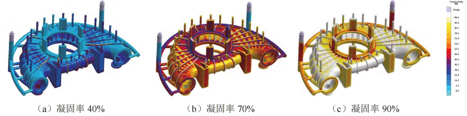
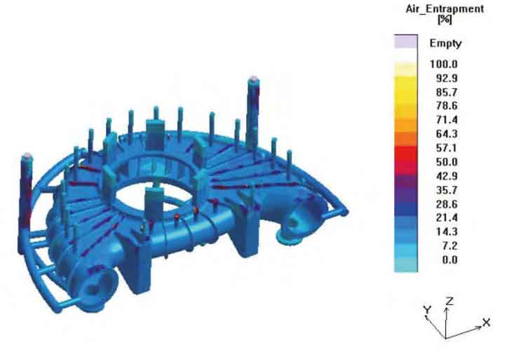
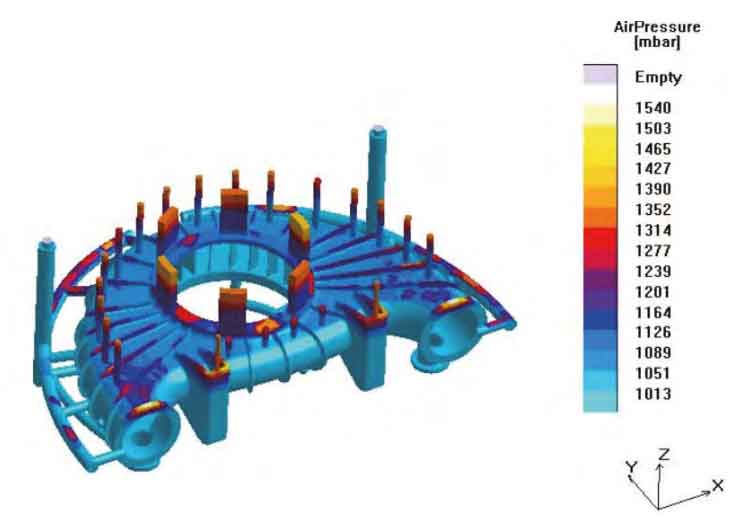
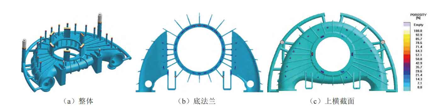
The main simulation results of Scheme 1 are shown in Figures 6-9:
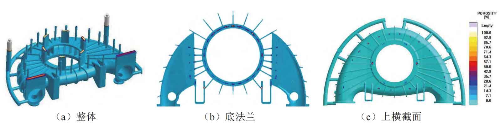
From the numerical simulation results, the advantages of Scheme 1 are: (1) simple process design and high yield; (2) Smooth filling. The disadvantages are: (1) there is a risk of poor filling and backflow of inclusions; (2) Poor feeding and shrinking ability of the riser; (3) There is a high risk of shrinkage defects in the bottom flange.
The advantages of Scheme 2 are: (1) good filling and shrinking ability; (2) Smooth filling and no risk of poor filling. The disadvantages are: (1) complex process design and low production rate; (2) There is a risk of air entrapment on the top of the casting; (3) There is a risk of shrinkage defects in the bottom flange, side flange, and top flange.
Based on the results of numerical simulation such as filling, solidification, and pressure changes, after comprehensive analysis, Plan 1 is determined as the final casting process plan. At the same time, in order to eliminate casting defects as much as possible, the feeding capacity of the riser has been increased, and the density of the casting has been increased by increasing the arrangement of local external cold iron, internal cold iron, and chromium iron ore sand to prevent casting defects such as cracks and shrinkage cavities.
2.2.3 Steel Melting and Composition Control
According to calculations, the total weight of the molten steel is 5.4-5.6 tons, which requires two 3-ton electric furnaces to be melted simultaneously. The pouring temperature should be controlled between 1590-1620 ℃, and the ladle should be baked above 800 ℃. After pouring, carbon free insulation agent should be added to cover it. After pouring for 48 hours, the box should be opened and sand should be dropped.
When melting titanium containing stainless steel, the titanium element is relatively active, with a yield of 40%~50%. During the melting and solidification process, it is easy to react with nitrogen to form harmful phase TiN. TiN not only affects the fluidity of the steel liquid, but also easily forms defects such as slag on the surface of the casting. Therefore, in order to reduce the nitrogen content in the molten steel, the proportion of stainless steel feed back should be reduced during melting, controlled within 20%. Choose 70 titanium iron as the titanium alloy, add it to the furnace for 2-3 minutes and immediately remove the steel. Before adding titanium iron, it must be deoxidized through silicon iron, manganese silicon calcium.
3. Production validation
On site production adopts alkaline phenolic resin bead sand molding and core making, and the sand mold cavity is coated with stainless steel alcohol based coating. The pouring temperature is controlled between 1600~1610 ℃. After the stainless steel volute casting is formed, the pouring and riser are cut off. After inspection, there are no casting defects such as cracks, pores, shrinkage holes, and slag inclusions that affect product quality inside the casting. As shown in Figure 14, the dimensions of the castings after mechanical processing meet the requirements of the drawings. The tensile specimens taken from the furnace test bars were tested for their mechanical properties, and the measured tensile strength was 490 MPa, yield strength was 215 MPa, elongation was 28%, and cross-sectional shrinkage was 35%, meeting the design requirements. In summary, this process measure is effective and correct, and can meet the requirements of mass production of products.