
The manufacturing of critical automotive components like brake drums demands processes that ensure high dimensional accuracy, superior metallurgical properties, and production efficiency. One advanced foundry technique that meets these rigorous requirements is sand coated iron mold casting. This process, fundamentally a hybrid method, combines the benefits of metal mold casting and sand casting, offering a unique solution for mass-producing high-integrity cast iron parts.
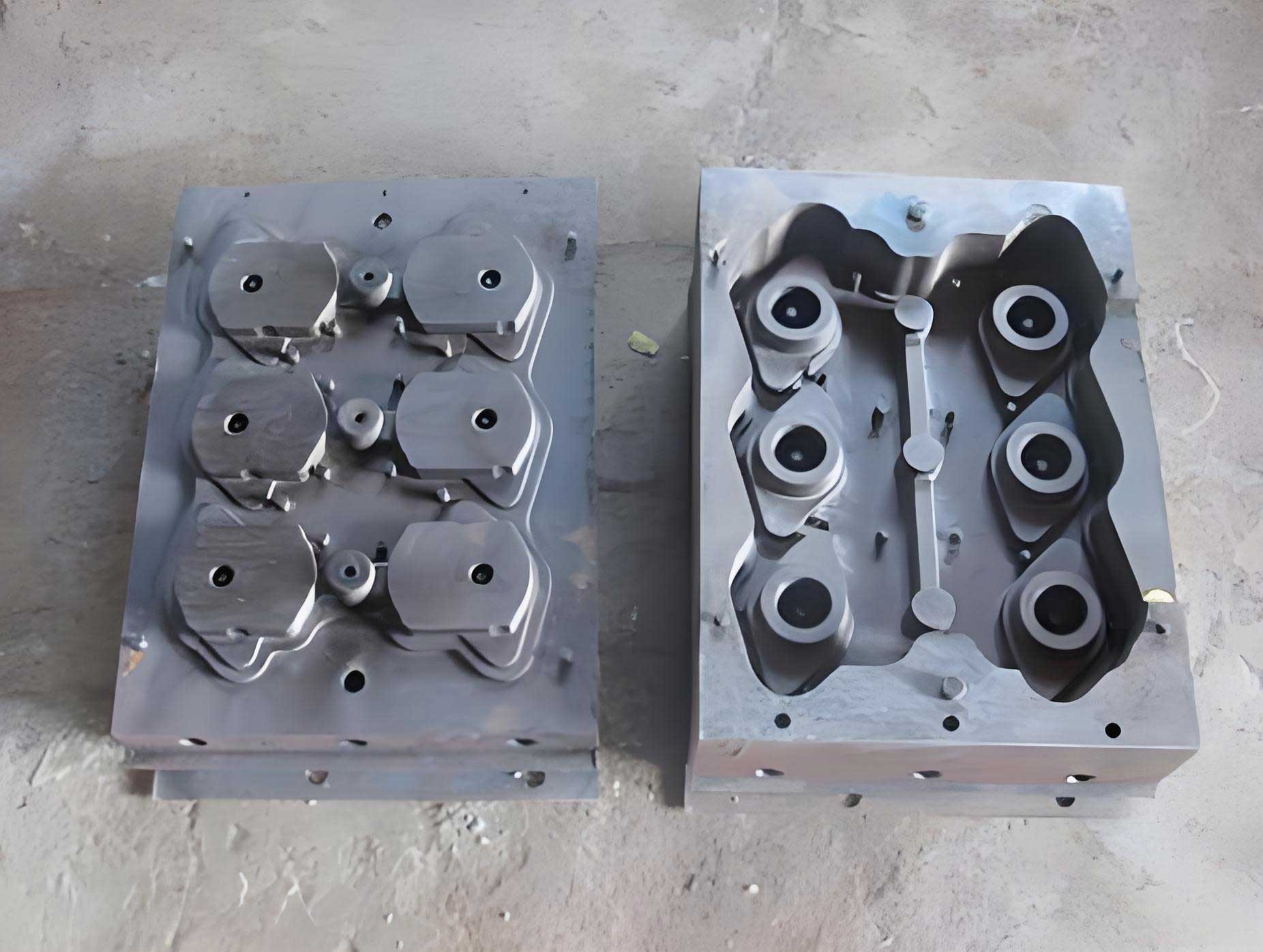
Sand coated iron mold casting involves creating a thin, hardened shell of resin-coated sand (typically 4–8 mm thick) on the inner surfaces of a pre-heated metal mold or flask. The metal mold, often referred to as the iron box or jacket, is heated to approximately 200–250°C. At this temperature field, the resin in the coated sand cures, forming a rigid, precise mold cavity. Molten iron is then poured into this cavity defined by the sand shell backed by the iron jacket. Upon solidification, the casting is ejected. The core principle leverages the high thermal conductivity of the metal mold, which acts as a powerful chilling agent, significantly accelerating the cooling rate of the molten metal. This rapid solidification refines the graphite structure, increases the density of the metallic matrix, and promotes a higher volume fraction of pearlite. Consequently, castings exhibit improved mechanical properties such as tensile strength and hardness. Furthermore, the rigid mold assembly, with its strong iron backing, effectively counteracts the expansion pressure generated by graphite precipitation during eutectic solidification. This phenomenon minimizes mold wall movement and facilitates excellent feeding characteristics through internal micro-expansion, allowing for the production of sound castings with minimal risers or even riserless designs. The process yields castings with superior dimensional accuracy, reduced machining allowances, lower scrap rates, and less cleaning effort compared to conventional green sand casting. A key visual representation of the setup is provided below:
Despite its advantages, the process requires significant upfront investment in metal tooling and is most economically viable for high-volume production of a limited product range, such as brake drums.
Process Design and Operational Considerations in Sand Coated Iron Mold Casting
Successful implementation of sand coated iron mold casting hinges on meticulous process design. Several critical parameters must be optimized to balance casting quality, tooling life, and cost.
1. Coating Thickness: The thickness of the resin sand coating is a primary control variable. It directly influences the cooling rate and the resultant microstructure and hardness of the casting. An excessively thick coating diminishes the chilling effect of the iron mold, approaching the cooling characteristics of a sand mold, and increases material cost. Conversely, a coating that is too thin causes excessive chilling, leading to high hardness, potential carbides, and machining difficulties. The design rule is to vary the thickness strategically: thicker coatings on machined surfaces to allow for softer skin, thinner coatings on non-machined areas and thermal hotspots to promote directional solidification. For complex or large castings, a slightly thicker overall coating may be necessary to ensure complete and uniform filling of the mold cavity by the sand during the blowing process, preventing weak spots due to premature resin curing.
2. Mold and Flask Design: The design of the metal flask and patterns must account for thermal management and mechanical function. Uniform heating of both the pattern plate and the iron flask is crucial to achieve consistent sand curing. Temperature gradients can lead to soft, uncured spots or over-cured, brittle zones in the sand shell. For tall castings, it is essential to incorporate “air vents” or permeable plugs at the bottom of the mold. During pattern withdrawal, these vents prevent the formation of a vacuum that could damage the fragile sand shell by suction. The parting line should be designed to make the upper and lower flask halves roughly equal in height, shortening the flow path for the sand during shooting and ensuring dense, uniform packing. Small exhaust channels, often simple saw cuts, must be machined on the contact surfaces of the flask (e.g., where it meets the pattern plate) to allow air to escape during sand filling without permitting sand loss.
3. Thermal Analysis: The thermal regime is central to this process. The heat extraction can be modeled considering the thermal properties of the mold materials. The solidification time ($t_s$) for a simple shape can be approximated using Chvorinov’s rule, but modified for the composite mold wall:
$$ t_s = B \left( \frac{V}{A} \right)^n $$
Where $V$ is casting volume, $A$ is surface area, $n$ is an exponent (often ~2), and $B$ is the mold constant. For a sand coated iron mold, $B$ is significantly smaller than for a pure sand mold due to the high thermal diffusivity ($\alpha$) of iron:
$$ \alpha = \frac{k}{\rho c_p} $$
where $k$ is thermal conductivity, $\rho$ is density, and $c_p$ is specific heat. The iron flask’s high $k$ value dominates the heat transfer, making $B$ dependent on the composite resistance: the sand coating resistance ($R_{sand} = \delta_{sand}/k_{sand}$) in series with the iron’s convective/conductive resistance.
Material Science: Controlling HT250 Brake Drum Composition
The target material for brake drums is typically a high-strength flake graphite iron like HT250 (minimum 250 MPa tensile strength on separately cast test bars). Achieving this specification consistently with the sand coated iron mold casting process requires precise control over chemistry and inoculation, as the rapid cooling inherently promotes a finer microstructure but also increases sensitivity to composition.
The desired as-cast microstructure is type A graphite (randomly oriented flakes) of length 3-5 (ASTM standard), in a matrix of predominantly pearlite with less than 5% ferrite or carbides. The key elements and their interactive roles are summarized below:
| Element | Role & Effect | Target Range (wt.%) | Control Rationale |
|---|---|---|---|
| Carbon (C) | Primary graphitizer. Defines graphite amount and matrix. High C increases fluidity but reduces strength. Low C promotes pearlite but risks chill and poor fluidity. | 3.4 – 3.6 | Balanced for strength in rapid cooling process. Upper range for fluidity in thin-shell mold. |
| Silicon (Si) | Strong graphitizer, reduces carbon solubility. Increases ferrite, coarsens graphite. Critical for carbon equivalent (CE). | 1.6 – 1.8 (Final) | Controlled via late inoculation. Base Si kept low (~0.8-1.0%) pre-inoculation to allow for effective treatment. |
| Manganese (Mn) | Pearlite stabilizer, strengthens matrix. Mild carbide promoter. | 0.7 – 0.9 | Ensures fully pearlitic matrix to meet hardness and strength targets. |
| Phosphorus (P) | Forms low-melting, brittle phosphide eutectic at grain boundaries. Harmful. | < 0.06 | Strictly limited via raw material selection (low-P pig iron, controlled returns). |
| Sulfur (S) | Dual role. Traditionally harmful (promotes chill, forms FeS). In low-S melts, acts as a mild inoculant by forming MnS particles. | 0.07 – 0.10 | Intentional addition (e.g., FeS) to synthetic melts to create nucleation sites. |
| Chromium (Cr) | Powerful carbide stabilizer and pearlite refiner. Increases strength and hardness significantly. | 0.3 – 0.45 | Precise low-alloying addition for achieving HT250 specification with higher C.E. Critical to avoid excessive hardness. |
The Carbon Equivalent (CE) is a vital parameter for predicting microstructure and casting behavior. It is calculated as:
$$ CE = \%C + \frac{\%Si + \%P}{3} $$
For the target composition, CE ranges from approximately 3.95 to 4.10. This is a relatively high CE for a 250 MPa grade, made possible by the chilling effect of the sand coated iron mold and the use of chromium. The process allows for higher CE (better castability) while still achieving the required strength.
A significant metallurgical challenge arises from the melting practice. When using medium-frequency induction furnaces to melt steel scrap and carburizer (“synthetic iron”), the melt undergoes prolonged superheating and intense electromagnetic stirring. This environment is detrimental to potential nucleation sites (e.g., fine graphite particles, oxide inclusions like SiO₂). These sites can dissolve or be eliminated through reactions such as:
$$ SiO_2 + 2C \rightarrow Si + 2CO \uparrow $$
This leads to a “clean,” nucleation-deficient melt with high undercooling tendency, resulting in hard castings with poor machinability. Therefore, a two-pronged approach is essential: 1) Controlled Sulfur Addition: Reintroducing S to ~0.08% provides MnS particles that act as heterogeneous nucleation substrates for graphite. 2) Powerful Inoculation: Late addition of FeSi-based inoculants (containing elements like Ca, Al, Sr, Zr) is critical to create instant, numerous nucleation sites in the undercooled melt. The effectiveness of inoculation ($\Delta T_{recalescence}$) is crucial and is monitored via thermal analysis.
The relationship between final composition and mechanical properties can be summarized from production data:
| Heat | Final Chemistry (wt.%) | Mechanical Properties | ||||||
|---|---|---|---|---|---|---|---|---|
| C | Si | Mn | S | Cr | CE | Tensile (MPa) | Hardness (HBW) | |
| 1 | 3.45 | 1.82 | 0.66 | 0.082 | 0.30 | 4.05 | 240-247 | 239-252 |
| 2 | 3.44 | 1.70 | 0.73 | 0.086 | 0.35 | 4.01 | 246-252 | 236-250 |
| 3 | 3.44 | 1.66 | 0.73 | 0.078 | 0.28 | 4.00 | 292 | 237-250 |
| 4 | 3.44 | 1.69 | 0.70 | 0.072 | 0.33 | 4.00 | 271-279 | 212-229 |
| 5 | 3.42 | 1.62 | 0.70 | 0.097 | 0.33 | 3.96 | — | 230-240 |
The data shows consistent achievement of target properties with the defined chemistry window. The occasional higher tensile strength (Heat 3) correlates with effective inoculation and possibly a lower actual CE.
Production Workflow and Quality Assurance
The production of brake drums via sand coated iron mold casting follows a streamlined but controlled sequence. The charge makeup, based on the specified chemistry, typically follows a ratio like:
| Material | Pig Iron | Steel Scrap | Returns | Carburizer | FeSi | FeMn | FeCr | FeS |
|---|---|---|---|---|---|---|---|---|
| Charge % | 20 | 60 | 20 | 2.25 | 1.4 | 0.4 | 0.5 | 0.16 |
Melting is conducted in a coreless induction furnace. After reaching a superheat temperature (e.g., 1500-1520°C), a sample is taken for quick thermal analysis or spark spectrometry to determine base carbon and silicon. Based on this readout, final adjustments are made. Key late additions include:
1. Carburizer (if C is low).
2. Manganese and Chromium additives to hit precise targets.
3. Sulfur addition (FeS) to adjust to the optimal range of 0.07-0.09%.
4. Inoculation: A potent inoculant (e.g., FeSi75 with special alloys) is added during tapping or in the pouring ladle at a rate of 0.2-0.4% of the metal weight. The inoculation process can be described by the increase in nuclei density ($N$), which is a function of inoculant type, addition rate, and melt handling:
$$ N = f(I_0, \eta, t_{hold}) $$
where $I_0$ is inoculant potency, $\eta$ is recovery/reaction efficiency, and $t_{hold}$ is time after addition before pouring (fading effect).
The treated iron is then poured into the prepared sand coated iron molds. The rapid heat extraction begins immediately. The solidification sequence favors a directional gradient from the iron mold wall inwards, suppressing shrinkage porosity. After a calculated cooling time, the casting is shaken out. The thin sand shell breaks away easily, and the casting requires minimal finishing. Each batch is validated through mechanical testing (tensile from separately cast keel blocks or from designated cast-on pads) and hardness checks on the casting body.
Conclusion and Process Advantages
The sand coated iron mold casting process stands out as a highly effective method for manufacturing high-performance gray iron components like brake drums. Its success lies in the synergistic combination of a precisely engineered sand shell and a high-conductivity metal mold. This synergy delivers:
$$ \text{Superior Properties} = \Phi_{\text{chill}} ( \text{Iron Mold} ) + \Pi_{\text{precision}} ( \text{Sand Shell} ) $$
where $\Phi_{\text{chill}}$ represents the chilling function leading to refined graphite (type A, size 3-5), increased pearlite fraction, and dense matrix, and $\Pi_{\text{precision}}$ represents the dimensional accuracy and surface finish imparted by the thin, rigid shell.
The process enables the use of a higher carbon equivalent for improved castability while still meeting stringent strength specifications like HT250, largely through controlled low-alloying (Cr) and optimized inoculation practices tailored to the nucleation-deficient environment of induction-melted synthetic iron. The rigid mold system harnesses graphitic expansion for self-feeding, dramatically reducing shrinkage defects and yield loss. While the initial capital investment for metal tooling is substantial, the benefits in consistent quality, reduced machining, high yield, and productivity for high-volume parts make sand coated iron mold casting a technically and economically superior choice for foundries specializing in automotive safety components.