
In the field of rail transit vehicle manufacturing, nodular cast iron components play a critical role due to their excellent mechanical properties, such as high strength and ductility. As a key material for brake system parts, nodular cast iron ensures reliable performance under dynamic loads. However, during the production of complex castings like brake cylinder blocks, shrinkage defects often arise, leading to high rejection rates in non-destructive testing. In this article, I will delve into a case study involving a nodular cast iron brake cylinder casting, where magnetic particle inspection revealed subsurface micro-shrinkage. Through detailed analysis and process optimization, significant improvements were achieved. The focus will be on the root causes of shrinkage in nodular cast iron, the use of simulation tools like MAGMA, and practical solutions that enhanced yield from below 50% to over 94%. Throughout, I will emphasize the unique challenges of working with nodular cast iron, a material prone to shrinkage due to its wide solidification range.
The brake cylinder casting discussed here is a compact component with varying wall thicknesses, designed for urban rail vehicles. Its geometry includes thin sections of 8 mm and thicker regions up to 45 mm, creating thermal gradients that complicate solidification. The material is nodular cast iron, grade QT500-7, which requires a predominantly pearlitic-ferritic matrix with spherical graphite to meet stringent standards. For quality assurance, full-surface magnetic particle inspection is mandated, with all machined and as-cast surfaces judged against level 2 criteria. Additionally, radiographic testing is applied to critical zones to detect internal flaws. These requirements underscore the importance of defect-free castings in safety-critical applications, where nodular cast iron’s properties must be fully realized without compromise.
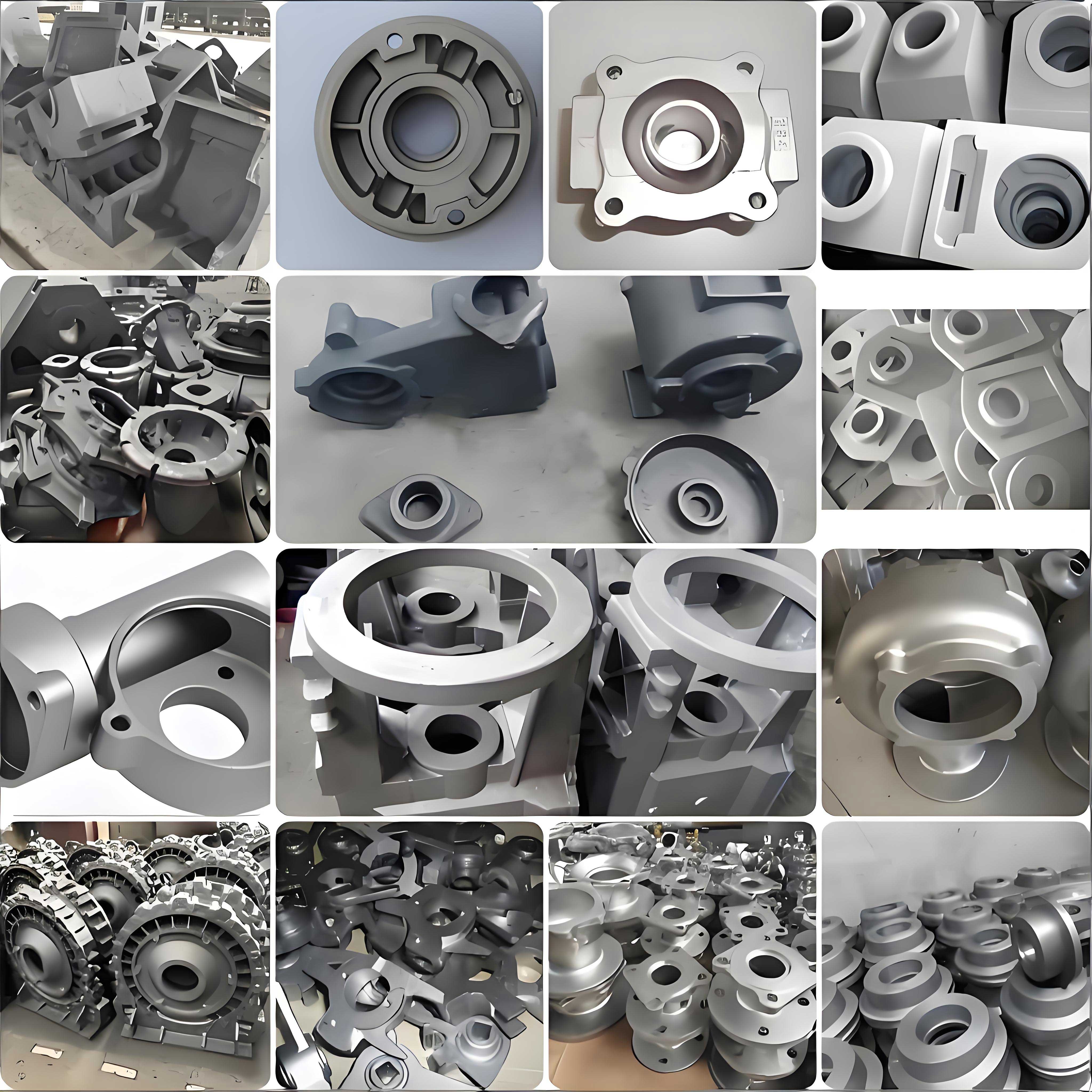
Initially, the casting process employed a shell mold technique using resin-coated sand, with melting conducted in a 3-ton medium-frequency induction furnace. The gating system was top-poured, with two castings per mold, and included four exothermic risers and two conformal chills to address shrinkage. The nodular cast iron was treated via the sandwich method with multiple inoculations: base inoculation, covering inoculation, and post-inoculation during pouring. The pouring temperature ranged from 1,340°C to 1,360°C, while the tapping temperature was between 1,450°C and 1,510°C. Despite these measures, mass production revealed a persistent issue: magnetic particle inspection showed clustered indications on the inner cavity sidewalls, specifically in areas oriented 45 degrees away from the runner. These indications, upon metallographic examination, were identified as micro-shrinkage voids, approximately 1,037 µm deep, dispersed in the nodular cast iron matrix. This defect pattern suggested inadequate feeding during solidification, a common problem in nodular cast iron due to its prolonged mushy zone.
To understand the defect mechanism, I analyzed the solidification behavior using MAGMA simulation software. The original process simulation predicted porosity risks in the sidewall regions beneath the chills, where isolated liquid pockets formed due to rapid cooling and insufficient feed metal. The simulation results aligned with the actual defect locations, indicating that the chills, while intended to promote directional solidification, were ineffective in providing adequate feeding paths. The fundamental issue stems from the solidification characteristics of nodular cast iron. Unlike other alloys, nodular cast iron exhibits a wide freezing range, which can be described by the following relation for shrinkage tendency:
$$ S = \int_{T_l}^{T_s} \frac{\partial f_s}{\partial T} dT $$
where \( S \) represents the shrinkage potential, \( T_l \) is the liquidus temperature, \( T_s \) is the solidus temperature, and \( f_s \) is the solid fraction. For nodular cast iron, the interval \( T_l – T_s \) is broad, leading to prolonged interdendritic feeding challenges and micro-porosity formation. Additionally, the modulus method, often used to design risers, can be expressed as:
$$ M = \frac{V}{A} $$
where \( M \) is the modulus (cooling rate factor), \( V \) is the volume, and \( A \) is the surface area. In thin-walled sections of the casting, such as the 8 mm sidewalls, the modulus is low, causing rapid solidification that hinders riser feeding. The original risers and chills failed to compensate for this, resulting in micro-shrinkage in the nodular cast iron.
Based on this analysis, I proposed two iterative improvements. The first modification replaced the conformal chills with exothermic risers identical to those used near the ingates, aiming to enhance feeding. However, simulation of this scheme showed that while the original defect zones improved, new porosity risks emerged between the additional risers. A small batch trial confirmed no significant gain in magnetic particle inspection pass rates, underscoring the complexity of feeding nodular cast iron castings. The second, more comprehensive redesign involved three key changes: switching from a top-gating to a bottom-gating system to promote smoother filling and temperature gradients; adding process allowances (padding) on the inner cavity walls to increase the modulus and improve feeding channels; and repositioning the casting to have the inner cavity facing downward, allowing for strategic placement of risers at top, middle, and bottom hotspots. Furthermore, conformal chills were reintroduced in the inner cavity to segment the feeding zones, ensuring that risers on each side fed specific regions without interference. The revised gating and risering layout was simulated again, and the results indicated complete elimination of shrinkage porosity. The effectiveness of these changes can be summarized in the following table comparing key parameters:
| Process Parameter | Original Process | Improved Process (Scheme II) |
|---|---|---|
| Gating Orientation | Top gating | Bottom gating |
| Number of Exothermic Risers | 4 | 6 |
| Chill Configuration | 2 conformal chills | 2 conformal chills (repositioned) |
| Process Allowances | None | Added on inner walls |
| Casting Orientation | Inner cavity up | Inner cavity down |
| Simulated Porosity Risk | High in sidewalls | Negligible |
| Magnetic Particle Inspection Pass Rate | ~50% | >94% |
The improved process was validated through mass production of over 3,700 nodular cast iron brake cylinder castings. The yield exceeded 94%, demonstrating the robustness of the changes. This success highlights the importance of integrating simulation tools with practical foundry knowledge to tackle shrinkage in nodular cast iron. For instance, the feeding distance in nodular cast iron can be estimated using empirical formulas that account for alloy properties and cooling conditions. One such formula is:
$$ L_f = k \cdot \sqrt{M} $$
where \( L_f \) is the feeding distance, \( M \) is the modulus of the section, and \( k \) is a constant dependent on the alloy type—typically lower for nodular cast iron due to its shrinkage tendencies. By increasing the modulus through padding and optimizing riser placement, the feeding distance was effectively extended, mitigating micro-shrinkage. Additionally, the solidification time \( t_s \) for a casting section can be approximated by:
$$ t_s = C \cdot \left( \frac{V}{A} \right)^2 $$
with \( C \) as a constant related to the mold material and metal properties. For nodular cast iron, longer solidification times in thicker sections can exacerbate shrinkage if not properly fed, hence the need for tailored riser design.
Beyond this specific case, the principles applied here are broadly relevant to nodular cast iron casting production. The material’s graphite formation during eutectic solidification introduces volume expansion that can offset shrinkage, but only if the process controls are precise. Inadequate inoculation or excessive cooling rates can destabilize this balance, leading to defects. Therefore, I recommend a holistic approach that combines thermal analysis, modulus calculations, and real-time process monitoring. For example, controlling the cooling rate \( \frac{dT}{dt} \) through chill design is critical; it can be modeled using Fourier’s heat conduction equation:
$$ \rho c_p \frac{\partial T}{\partial t} = \nabla \cdot (k \nabla T) + Q $$
where \( \rho \) is density, \( c_p \) is specific heat, \( k \) is thermal conductivity, and \( Q \) represents latent heat release during solidification of nodular cast iron. By solving this numerically in simulations, optimal chill sizes and locations can be determined to direct solidification fronts toward risers.
In conclusion, the defect analysis and process optimization for the nodular cast iron brake cylinder casting underscore the challenges inherent in producing high-integrity nodular cast iron components. Through systematic investigation using metallography and solidification simulation, micro-shrinkage was identified as the root cause of magnetic particle inspection failures. The implemented improvements—including a bottom gating system, process allowances, and redesigned riser and chill layouts—effectively eliminated these defects, boosting yield significantly. This case study serves as a testament to the value of integrating advanced simulation tools with empirical foundry practices to enhance the quality of nodular cast iron castings. Future work could explore further refinements, such as dynamic feeding controls or alloy modifications, to push the boundaries of nodular cast iron performance in demanding applications.