
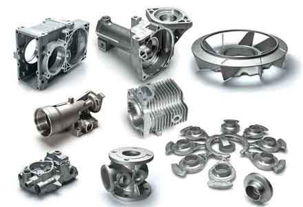
The casting industry, as a fundamental and vital traditional sector, maintains an irreplaceable position in both developed and developing nations. For the production of sand casting parts, the design of casting technology is the core and preliminary step, determining the ultimate quality, production rate, and cost. Conventional design methods are heavily reliant on empirical judgment and iterative trial production, leading to high consumption, elevated costs, low efficiency, and suboptimal yield rates. These characteristics place foundries at a significant disadvantage in today’s fiercely competitive market. Consequently, the transition from experiential judgment to quantitative analysis represents a crucial trend in advanced manufacturing. Computer numerical simulation stands as a pivotal method and pathway to achieve this goal, marking a shift for the foundry industry from qualitative to quantitative and from experience-based to scientific research.
This study focuses on the numerical simulation of the forming process for sand casting parts. By employing computer simulation technology, the entire dynamic process of mold filling and solidification can be visualized and analyzed before actual production. This enables the prediction of potential defects such as shrinkage porosity, hot tears, cold shuts, and gas entrapment, providing a scientific basis for optimizing gating and risering systems, controlling defects, and ultimately achieving the goals of high quality, efficiency, low cost, and cleanliness. The research content and methodology presented herein possess broad applicability, offering a reference for further studies in related areas and holding substantial practical significance and value for real-world production applications.
1. Development and Foundation of Casting Simulation
The computer simulation of casting processes is a frontier domain in the global foundry industry’s development. It involves the intersection of information science, materials science, engineering mechanics, and computer graphics, forming a critical component of modern manufacturing science. The core of casting process numerical simulation lies in the analysis of the flow field and temperature field during mold filling, as well as the temperature and stress fields during solidification. Through simulation, the flow state of molten metal within the gating system and mold cavity can be analyzed to optimize design, prevent defects related to fluid dynamics, and predict thermal defects related to solidification.
Globally, research in this field began as early as the 1960s, with initial applications of finite difference methods (FDM) for solidification heat transfer calculations. With the rapid advancement of computer technology, particularly since the 1990s, three-dimensional numerical simulation software has matured. Various commercial casting simulation software packages have been developed and widely applied in practice.
| Software Name | Core Numerical Method | Primary Application Scope | Key Features |
|---|---|---|---|
| Magmasoft | Finite Difference Method (FDM) | Sand casting, Die casting, Investment casting | Integrated simulation of filling, cooling, solidification; module for mold stress analysis. |
| ProCAST | Finite Element Method (FEM) | Sand casting, Die casting, Investment casting, Lost foam, etc. | Coupled fluid flow, heat transfer, and stress analysis; strong capabilities in microstructure and inverse modeling. |
| FLOW-3D | Volume of Fluid (VOF) / FDM | Die casting, Sand casting, Investment casting | Specializes in high-fidelity free surface flow tracking; detailed modeling of surface defects. |
| AnyCasting | FDM / FEM | Various casting processes | User-friendly interface; fast calculation speed; good cost-performance ratio. |
| InteCAST (Huazhu CAE) | FDM | Sand casting, Die casting, Low-pressure casting | Domestically developed software in China; widely used in local foundries for process optimization. |
The future of casting simulation technology is anticipated to evolve in several key directions: achieving more accurate predictions of a wider range of defects (including hot tearing and distortion), integrating microstructural modeling with macro-properties prediction, establishing more comprehensive and accurate material property databases, and moving towards a networked, parallel system that integrates design, simulation, manufacturing, and evaluation for rapid product development.
2. Theoretical Models for Numerical Simulation
The success and accuracy of numerical simulation depend fundamentally on the mathematical models established to describe the physical phenomena. For sand casting parts, the forming process involves coupled phenomena of fluid flow, heat transfer, and stress development, each governed by its own set of conservation equations.
2.1 Modeling of Mold Filling Process
The mold filling process for molten metal is a transient, incompressible viscous fluid flow problem, often involving a moving free surface (the interface between molten metal and air). It is governed by the fundamental laws of conservation of mass, momentum, and energy.
The continuity equation (mass conservation) for an incompressible fluid is:
$$ \nabla \cdot \vec{u} = 0 $$
where $\vec{u}$ is the velocity vector.
The momentum conservation is described by the Navier-Stokes equations:
$$ \rho \left( \frac{\partial \vec{u}}{\partial t} + (\vec{u} \cdot \nabla) \vec{u} \right) = -\nabla p + \mu \nabla^2 \vec{u} + \rho \vec{g} $$
where $\rho$ is density, $t$ is time, $p$ is pressure, $\mu$ is dynamic viscosity, and $\vec{g}$ is gravitational acceleration.
The energy equation (heat transfer) during filling is:
$$ \rho c_p \left( \frac{\partial T}{\partial t} + (\vec{u} \cdot \nabla) T \right) = \nabla \cdot (k \nabla T) + S $$
where $c_p$ is specific heat capacity, $T$ is temperature, $k$ is thermal conductivity, and $S$ is a source term (e.g., for latent heat during solidification, typically activated after filling).
A critical aspect of filling simulation is tracking the evolution of the free surface. The Volume of Fluid (VOF) method is commonly used, where a volume fraction function $F$ is defined (F=1 in metal, F=0 in air, 0<f<1 $$="" $k-\epsilon$="" (\vec{u}="" (rans)="" +="" \cdot="" \frac{\partial="" \nabla="" are="" at="" effects,="" equation="" equations="" f)="0" fast="" filling,="" f}{\partial="" in="" interface).="" is:="" its="" like="" model.
2.2 Modeling of Solidification Process
After filling, the solidification process dominates, which is primarily a transient heat conduction problem with a moving phase change boundary (the mushy zone). The governing energy equation is:
$$ \rho \frac{\partial H}{\partial t} = \nabla \cdot (k \nabla T) $$
Here, $H$ is enthalpy, which elegantly incorporates the latent heat $L$ released during phase change:
$$ H = \int_{T_{ref}}^T \rho c_p \, dT + \rho L (1 – f_s) $$
where $f_s$ is the solid fraction, a function of temperature. For a binary alloy, it can be approximated by the Scheil equation under non-equilibrium conditions:
$$ f_s = 1 – \left( \frac{T_m – T}{T_m – T_l} \right)^{\frac{1}{k_0 – 1}} $$
where $T_m$ is the melting point of the solvent, $T_l$ is the liquidus temperature, and $k_0$ is the equilibrium partition coefficient.
The accurate prediction of shrinkage defects (macro-porosity and micro-porosity) is a primary goal of solidification simulation. The Niyama criterion is a widely used empirical criterion for predicting the tendency for shrinkage porosity in castings:
$$ \frac{G}{\sqrt{\dot{T}}} \leq C_{Niyama} $$
where $G$ is the temperature gradient, $\dot{T}$ is the cooling rate, and $C_{Niyama}$ is a material-dependent constant. Regions where this value falls below the critical threshold are prone to shrinkage porosity.
2.3 Modeling of Stress Development
Thermal stresses in sand casting parts arise due to non-uniform cooling and the mechanical constraint from the mold. Stress analysis is typically performed using a decoupled approach: the temperature history from the thermal analysis is used as a thermal load for the mechanical analysis. A thermo-elasto-plastic constitutive model is often employed.
The total strain increment $\{d\epsilon\}$ is decomposed into elastic, plastic, and thermal components:
$$ \{d\epsilon\} = \{d\epsilon^e\} + \{d\epsilon^p\} + \{d\epsilon^{th}\} $$
The thermal strain increment is given by:
$$ \{d\epsilon^{th}\} = \alpha \{dT\} $$
where $\alpha$ is the coefficient of thermal expansion. The stress increment is related to the elastic strain increment by Hooke’s law:
$$ \{d\sigma\} = [D^e] \{d\epsilon^e\} = [D^e] (\{d\epsilon\} – \{d\epsilon^p\} – \{d\epsilon^{th}\}) $$
where $[D^e]$ is the elastic stiffness matrix, which is temperature-dependent. Plastic deformation occurs when the stress state satisfies a yield criterion. The von Mises yield criterion is commonly used:
$$ \sigma_{eff} = \sqrt{\frac{1}{2}[(\sigma_1-\sigma_2)^2 + (\sigma_2-\sigma_3)^2 + (\sigma_3-\sigma_1)^2]} \geq \sigma_y(T) $$
where $\sigma_{eff}$ is the effective stress, $\sigma_{1,2,3}$ are principal stresses, and $\sigma_y(T)$ is the temperature-dependent yield strength. When yielding occurs, the plastic strain increment is determined by a flow rule (e.g., associated flow rule) and a hardening law.
The boundary condition at the casting-mold interface is complex, involving heat transfer across potential air gaps and mechanical contact/friction. For sand casting parts, the mold is often assumed to have a “yielding” behavior, and its mechanical constraint is sometimes simplified or modeled using contact algorithms in finite element analysis.
3. Practical Application: Simulation and Optimization of a Flywheel Casting
To demonstrate the practical application of numerical simulation in optimizing the process for sand casting parts, a case study of a flywheel casting is presented. The material is ductile iron QT450-10, and the initial production trials encountered severe internal shrinkage porosity, failing quality inspections.
3.1 Geometric Modeling and Preprocessing
The three-dimensional geometric model of the flywheel, including the part, gating system (down sprue, runners, and ingates), and riser, was created using Pro/ENGINEER software. The mold and core were also modeled as separate volumes. A critical step in the simulation workflow is the interface between CAD and CAE software. This study employed an efficient method: using the Pro/MECHANICA module within Pro/ENGINEER to generate a surface mesh of the assembly, which was exported in ANSYS format (.ans). This file was then directly imported into the MeshCAST module of ProCAST for automatic tetrahedral volume mesh generation. This approach proved more robust and less time-consuming than repairing and meshing complex native CAD geometry directly within MeshCAST.
3.2 Initial Process Simulation and Defect Analysis
The initial gating system was designed with multiple ingates aiming for simultaneous filling. Simulation parameters were set: pouring temperature of 1380°C, mold initial temperature of 25°C, interfacial heat transfer coefficient (HTC) between casting and sand mold of 500 W/(m²·K). The filling analysis revealed turbulent flow and potential air entrapment. More critically, the solidification simulation showed that the feeding paths from the riser to the heavy sections of the flywheel solidified prematurely, isolating those sections and preventing effective liquid metal feeding. The Niyama criterion and fraction solid analysis clearly predicted extensive shrinkage porosity in the hub and web areas of the flywheel, as shown in the simulation results. This correlated perfectly with the defects found in the initial trial castings.
3.3 Process Optimization Based on Simulation
To address the shrinkage problem, the principle of directional solidification was applied. The gating and risering system was redesigned in Pro/ENGINEER:
- Riser Modification: A larger, more efficiently shaped riser was placed adjacent to the heaviest thermal center (hub) of the flywheel to act as a liquid metal reservoir.
- Use of Chills: Three external chills (made of H13 steel) were strategically placed on the sand mold around thick sections of the flywheel rim. Their function is to increase the local cooling rate, creating a favorable temperature gradient that promotes directional solidification towards the riser.
- Gating Adjustment: The ingate locations were adjusted to ensure a smoother filling pattern and to align with the new thermal gradients.
The modified 3D model was re-meshed, and the simulation was rerun with the chills included (assigning them appropriate material properties and HTCs).
3.4 Results of Optimized Simulation
The new simulation results demonstrated a significant improvement. The solidification sequence clearly showed that the chills accelerated the cooling of the rim, while the main body of the flywheel and the feeding path remained liquid for a longer time. The liquid metal in the riser was now able to effectively feed the shrinkage in the flywheel hub throughout the solidification process. The predicted shrinkage porosity was drastically reduced and was confined to non-critical areas, such as the ingate junctions, which would be removed during machining. The optimized process was adopted for production, and the resulting sand casting parts passed the X-ray inspection, meeting all quality requirements and confirming the validity of the simulation-guided optimization.
| Aspect | Initial Process | Optimized Process |
|---|---|---|
| Riser Design | Smaller, inefficient | Larger, placed at thermal center |
| Auxiliary Cooling | None | Three steel chills on the rim |
| Solidification Mode | Near-simultaneous, isolated hot spots | Directional, towards the riser |
| Simulated Shrinkage | Extensive in hub and web | Minimal, localized to ingates |
| Actual Casting Quality | Failed X-ray inspection | Passed X-ray inspection |
4. Specialized Study on Stress Field Simulation for Sand Casting Parts
While ProCAST has an integrated stress module, the study of thermal stress development is a complex and specialized field. To gain deeper insight and explore methodologies, a separate investigation was conducted using the general-purpose finite element analysis software ANSYS on a classic “stress frame” casting. This component, consisting of thick and thin sections connected, is prone to developing residual stresses due to differential cooling and is an excellent benchmark for stress simulation.
4.1 Methodology with ANSYS
A 3D model of the ZG25 carbon steel stress frame and its sand mold was created. The analysis was performed using a sequentially coupled thermal-stress method in ANSYS.
- Thermal Analysis: A transient thermal analysis was first conducted to obtain the temperature history of the entire system. Temperature-dependent thermal properties (conductivity $k(T)$, specific heat $c_p(T)$, and enthalpy) for both the steel and the sand were input. Boundary conditions included convective heat loss from the mold exterior and initial temperatures (1678°C for metal, 20°C for mold).
- Structural Analysis: The nodal temperature histories from the thermal analysis were imported as body loads into a separate structural model. Temperature-dependent mechanical properties were crucial: Elastic modulus $E(T)$, yield strength $\sigma_y(T)$, Poisson’s ratio $\nu(T)$, coefficient of thermal expansion $\alpha(T)$, and a bilinear kinematic hardening model were defined. A thermo-elasto-plastic material model was used. The sand mold was included in the model, and contact elements with appropriate properties (friction) were defined at the casting-mold interface to simulate mechanical interaction.
4.2 Stress Simulation Results and Findings
The ANSYS simulation successfully captured the dynamic evolution of stress during the cooling of the stress frame. In the early stages, the thin section cooled and contracted faster than the thick section. Because they are connected, the thin section was pulled in tension by the hotter, larger thick section, while the thick section was compressed. At an intermediate time, the tensile stress in the thin section and compressive stress in the thick section reached a maximum. In later stages, as the thick section finally began to cool and contract more rapidly, the stress state reversed: the thin section went into compression, and the thick section went into tension. This final tension in the thick section often manifests as the “residual stress” after complete cooling. The simulation results aligned well with established theoretical understanding of stress development in such constrained castings.
4.3 Comparative Analysis and Interface Exploration
The same stress frame was also simulated using ProCAST’s integrated thermal-stress capability. The overall trends in temperature and stress evolution were consistent between the ANSYS and ProCAST results, validating the general approach. However, this exercise highlighted the complementary strengths of specialized tools: ProCAST offers a more streamlined, casting-focused workflow for coupled filling-solidification-stress analysis, while ANSYS provides extremely granular control over material models, element types, and boundary conditions for advanced mechanical analysis.
This comparison prompted an investigation into the potential for linking the two software packages. The concept involves using ProCAST for the comprehensive casting process simulation (filling, solidification, and an initial stress calculation) and then exporting the resulting residual stress field to serve as an initial condition/pre-stress in ANSYS for subsequent detailed structural analysis (e.g., simulating machining distortion or in-service loading). The key technical challenges involve:
- Mesh and Data Mapping: Accurately transferring nodal stress data from ProCAST’s tetrahedral mesh to ANSYS’s potentially different mesh (e.g., hexahedral).
- File Format Conversion: Developing a translator to convert ProCAST’s stress output into an ANSYS-readable format (like an initial stress file).
A conceptual framework for this interface was established, outlining the necessary steps for data extraction, processing, and import, paving the way for future implementation to leverage the strengths of both simulation environments for the analysis of sand casting parts.
| Feature | ANSYS Approach | ProCAST Approach |
|---|---|---|
| Analysis Type | Sequentially Coupled Thermal-Stress | Integrated or Sequentially Coupled within one environment |
| Material Model Flexibility | Very High (user-defined, complex plasticity/creep) | High (tailored for casting alloys, but less general than ANSYS) |
| Boundary Condition Control | Granular control over contact, friction, constraints | Simplified or tailored interfaces for casting-mold interaction |
| Primary Strength | Advanced structural mechanics, multiphysics | Integrated foundry process simulation (flow+solidification+stress) |
| Workflow for Casting | More steps required (thermal then structural model setup) | Streamlined, all steps within a casting-oriented interface |
5. Conclusions and Future Perspectives
This study comprehensively investigated the numerical simulation of the forming process for sand casting parts, from theoretical foundations to practical application and specialized stress analysis. The key conclusions are as follows:
1. Practical Optimization is Achievable: Using ProCAST software, the filling and solidification process of a problematic flywheel casting was successfully simulated. The software accurately predicted the location and severity of shrinkage defects. Based on these insights, the gating and risering system was optimized by incorporating a larger riser and strategic use of chills to enforce directional solidification. The revised process was validated by simulation and subsequently by successful production, demonstrating that numerical simulation is a powerful and reliable tool for optimizing the manufacturing of sand casting parts, reducing development cost and time while improving quality.
2. Stress Analysis Provides Deeper Insight: The thermal stress development during solidification and cooling is critical for predicting distortion and hot tearing. A separate, detailed stress analysis of a benchmark stress frame casting was conducted using ANSYS. Employing a sequentially coupled thermo-elasto-plastic model with temperature-dependent properties, the simulation captured the dynamic reversal of stresses between thick and thin sections, aligning with theoretical expectations. This confirms the feasibility of using finite element methods for residual stress prediction in sand casting parts.
3. Software Integration Holds Potential: A comparative study between ProCAST and ANSYS revealed consistent trends in stress results. This finding underpins the conceptual development of an interface framework between the two software packages. The proposed link aims to leverage ProCAST’s strengths in complete casting process simulation to generate accurate initial residual stress fields, which can then be imported into ANSYS for more advanced structural analyses (e.g., fatigue, impact, or machining simulation). This integration represents a promising direction for a more comprehensive digital design and analysis loop for cast components.
4. Foundational Workflow was Established: An efficient pre-processing workflow was identified, using Pro/ENGINEER with its Mechanica module for robust surface mesh generation, which is then seamlessly imported into ProCAST for volume meshing. This method effectively solves common geometry translation and repair challenges.
Future Work:
While this study provides a solid foundation, several avenues for further research and development exist:
- Microstructural Simulation: Extending the simulation to predict the as-cast microstructure (e.g., grain size, morphology) of sand casting parts based on local thermal history, and linking this to final mechanical properties, would represent a significant advancement towards true “virtual material” prediction.
- Implementation of Software Interface: The conceptual framework for linking ProCAST and ANSYS requires practical implementation. Developing the necessary data translators and mapping algorithms to enable a seamless transfer of residual stress data is a crucial next step.
- Expansion of Material Databases: The accuracy of simulation is directly dependent on the input material properties. Building comprehensive, reliable, and temperature-dependent thermophysical and mechanical property databases for a wider range of casting alloys (especially newer lightweight alloys like those of magnesium and high-performance aluminum) is essential for broadening the applicability of simulation technology.
- Validation and Uncertainty Quantification: Increased efforts in quantitatively validating simulation predictions against detailed experimental measurements (e.g., using thermocouples, distortion scanning, neutron diffraction for stress) and developing methods to quantify uncertainty in simulation results would further enhance industry confidence and adoption.
In summary, the numerical simulation of sand casting parts forming processes has evolved from a research topic to an indispensable engineering tool. By enabling virtual prototyping and optimization, it significantly shortens development cycles, reduces costs, minimizes defects, and ensures the production of high-integrity cast components, thereby driving innovation and competitiveness in the modern foundry industry.
</f