
In my extensive research into metal casting processes, I have dedicated significant effort to understanding and optimizing sand casting, particularly for large and complex components like machine tool beds. The quality of sand casting products hinges on numerous factors, but one of the most critical is the control of the molten metal filling speed during the mold cavity filling stage. Improper filling velocity can induce severe defects such as deformation, hot tears, and stress concentrations, ultimately compromising the mechanical integrity and surface finish of the final castings. This deterioration directly impacts the performance and longevity of high-value sand casting products like machine beds. My work, therefore, centered on developing and simulating a precision control system to minimize filling speed errors, thereby enhancing the reliability and quality of sand cast components.
Sand casting remains a dominant manufacturing method for a vast array of industrial parts, from small intricate pieces to massive structural elements like engine blocks and, pertinent to my study, machine tool beds. The versatility and cost-effectiveness of sand casting make it indispensable for producing diverse sand casting products. However, achieving consistency in complex sand casting products is challenging. The gravity-fed nature of the process means that the hydrodynamic behavior of the molten metal is paramount. While simulation software has been widely adopted to predict flow patterns and defects, my investigation revealed a gap in the direct, real-time control methodologies applied to the filling phase itself. Previous studies often focused on post-design simulation for parameter optimization, but fewer addressed the active control of the pouring process to enforce these optimal parameters. This motivated my research into employing Programmable Logic Controller (PLC) systems for this precise task. The goal was to move beyond passive prediction to active, stable control, ensuring every batch of sand casting products meets stringent quality standards.
The journey began with a thorough analysis of the complete sand casting workflow for a machine tool bed. My first-hand experience in foundry environments informed this breakdown. The process is sequential and must be meticulously planned. Below is a detailed summary table of the key stages I analyzed and their critical parameters for producing high-quality sand casting products.
| Process Stage | Key Activities & Equipment | Critical Parameters & Control Objectives | Impact on Final Sand Casting Products |
|---|---|---|---|
| Pattern & Core Making | Designing CAD models; creating wood/metal patterns; forming cores with resin-bonded sand. | Pattern dimensions (allowance for shrinkage); core gas permeability; core strength. | Determines the geometric accuracy and internal soundness of the cast bed. |
| Mold Assembly | Placing patterns in flasks; packing molding sand; setting cores; assembling cope and drag. | Mold hardness; venting channel placement; mold integrity. | Prevents mold wall movement and gas defects during pouring. |
| Melting & Pouring | Melting iron/steel in furnace; transferring to ladle; pouring into mold sprue. | Metal composition; pouring temperature (Tp); Filling Speed (v). | Most critical phase for defect formation. Uncontrolled speed causes turbulence and dross. |
| Solidification & Cooling | Allowing metal to solidify in mold; controlled cooling to room temperature. | Solidification time; cooling rate gradient. | Governs microstructure, mechanical properties, and residual stress. |
| Shakeout & Finishing | Breaking the sand mold; removing gates and risers; shot blasting; grinding. | Shakeout time; finishing techniques. | Affects the surface quality and dimensional tolerances of the finished product. |
My focus zeroed in on the pouring stage. To control it, one must first model it mathematically. The filling of a sand mold is fundamentally a transient fluid flow problem. For a gating system where the sprue height is constant during the filling of the cavity below the ingate, the driving pressure head is steady. Applying Bernoulli’s principle and accounting for energy losses, I derived the governing equation for the metal velocity at the ingate exit. The pressure head loss, Δh, is typically expressed as a function of the flow velocity and a system resistance coefficient.
The fundamental equation for the theoretical outflow velocity from the ingate, before entering the mold cavity, is given by:
$$ v = \sqrt{\frac{2gH}{1+\lambda}} $$
where:
- v is the molten metal velocity at the ingate exit (m/s),
- g is the acceleration due to gravity (9.81 m/s²),
- H is the effective static pressure head from the sprue top (m),
- λ is the total resistance coefficient of the gating system, encompassing friction and form losses.
However, this represents an ideal, loss-free scenario. In practice, for a real-time control system, the relationship between the actuating signal (e.g., ladle tilt or stopper rod position) and the actual flow rate into the mold is dynamic. The mass flow rate \dot{m} through the ingate can be described as:
$$ \dot{m}(t) = \rho A_{ingate} \cdot v(t) = \rho A_{ingate} \sqrt{\frac{2gH(t)}{1+\lambda(t)}} $$
where \rho is the metal density, A_{ingate} is the cross-sectional area of the ingate, and H(t) and \lambda(t) can be time-varying as the mold fills. This equation formed the theoretical backbone for my control algorithm. The challenge was to maintain v(t) or \dot{m}(t) at a desired setpoint despite these variations, ensuring laminar filling for superior sand casting products.
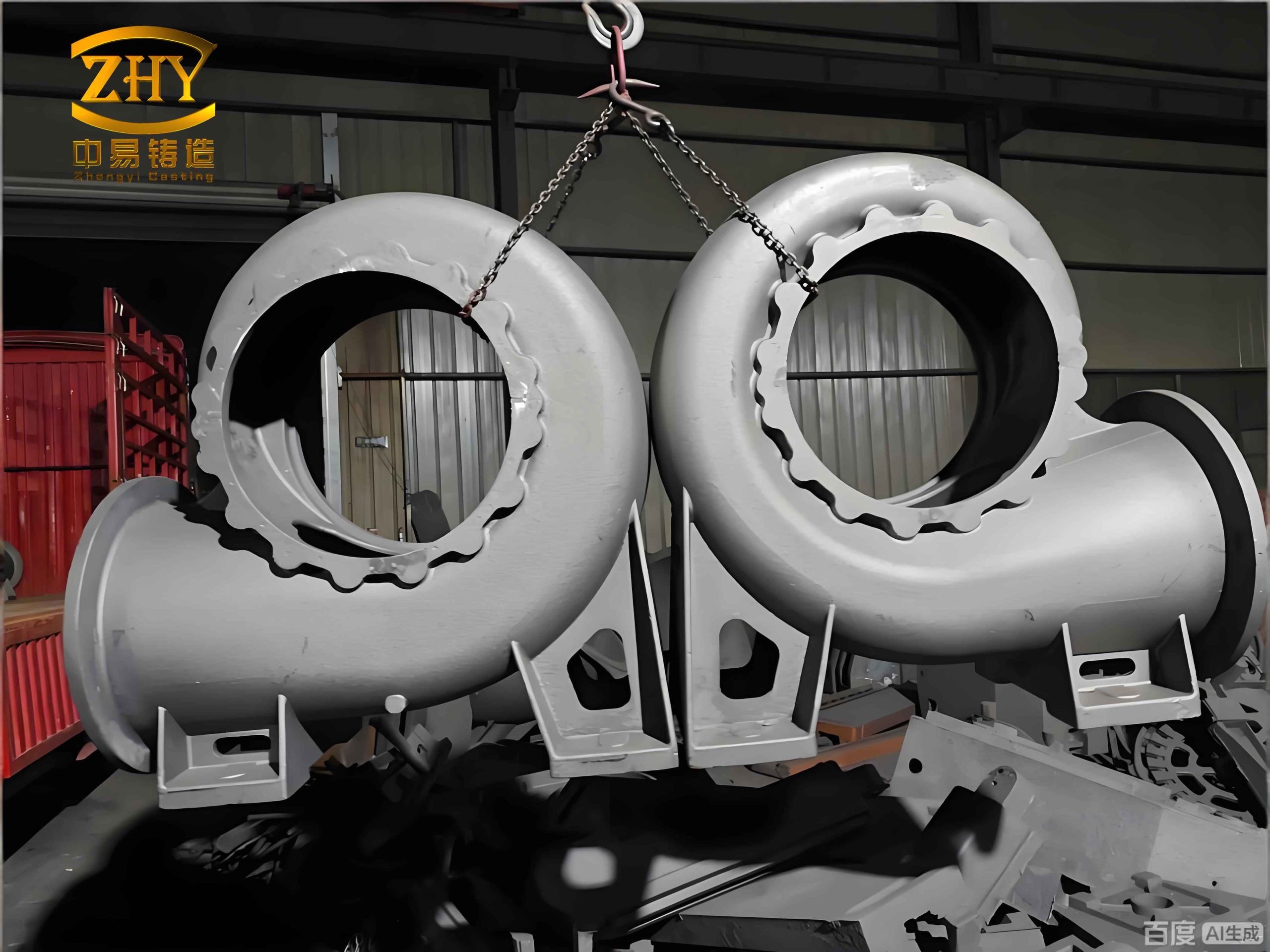
Observing various sand casting products during production, it became clear that manual or simple proportional-integral (PI) control of the pouring process was insufficient. The nonlinearities and disturbances called for a more robust approach. I turned to PLC-based control due to its reliability, flexibility, and precision in industrial environments. My design involved creating a dedicated hardware and software architecture. The software was structured into two main modules: a monitoring program for real-time data acquisition and processing, and an interface management program for handling communication protocols and executing control commands. I used ladder logic for programming due to its intuitive representation of relay circuits, which aligns well with industrial electricians’ expertise. The control logic was designed to read the desired filling speed setpoint, compare it with the measured real-time speed, and compute a corrective action for the actuator.
The hardware configuration was built around a central PLC unit. I selected modules for specific functions to create a cohesive measurement and control system. The configuration is summarized in the table below, which outlines how each component contributes to stabilizing the filling process for consistent sand casting products.
| PLC Module | Type/Model Example | Primary Function in Control Loop |
|---|---|---|
| Central Processing Unit (CPU) | CPU Module (e.g., CQM1-CPU41) | Executes the control program, processes logic, and manages data flow between modules. |
| Analog Input Module | High-speed Counter (connected to encoder) | Receives pulse signals from a flow sensor (e.g., turbine flow meter with encoder) to calculate real-time flow rate and speed. |
| Digital Input Module | DC Input Module (e.g., D212) | Reads status from start/stop buttons, emergency stops, and limit switches. |
| Analog Output Module | D/A Converter Module (e.g., DA021) | Sends the computed control signal (e.g., 4-20 mA) to the final control element (e.g., servo valve on ladle stopper). |
| Digital Output Module | Relay Output Module (e.g., OC22) | Controls auxiliary devices like indicator lamps, alarms, and relay coils for actuators. |
| Power Supply | PS Module (e.g., PS02) | Provides stable DC power to the PLC backplane and connected modules. |
| Human-Machine Interface (HMI) | Touch Panel or LED Display Board | Displays setpoint speed, actual speed, errors, and system status for operator interaction. |
The control principle is a closed-loop system. The turbine flow meter, installed in the runner system, generates pulse signals proportional to the volumetric flow rate. The PLC’s high-speed counter module captures these pulses. The CPU then calculates the instantaneous filling speed vactual(t). This value is compared to the preset optimal speed vset, derived from simulation studies. The error e(t) = vset – vactual(t) is fed into my custom control algorithm. Unlike a standard PI controller, my PLC algorithm incorporated additional logic to handle nonlinear actuator response and sudden disturbances, such as slag blocking the gate. The output adjusts the analog signal to the pouring mechanism, creating a dynamic equilibrium to keep the error minimal. This precise regulation is vital for preventing turbulence, which is a common culprit for oxide inclusions and mistruns in sand casting products.
To validate the superiority of my PLC-based approach, I conducted comprehensive error simulation studies, comparing it against a conventional PI controller. I used MATLAB/Simulink environment to build a dynamic model of the filling process. The model incorporated the fluid dynamics equations, thermal properties of the molten metal (gray iron), and the characteristics of the control actuators. The key simulation parameters, based on typical foundry data for machine bed castings, are listed below.
| Parameter Symbol | Description | Value / Range | Remarks |
|---|---|---|---|
| T | Pouring Temperature | 1400 °C | Critical for fluidity and solidification front. |
| ρ | Metal Density (Molten Iron) | 7.0 × 10³ kg/m³ | Affects momentum and thermal mass. |
| Cp | Specific Heat Capacity | 850 J·kg⁻¹·K⁻¹ | Influences heat transfer during filling. |
| kmetal | Thermal Conductivity | 47.2 W·m⁻¹·K⁻¹ | Governs rate of heat loss to sand mold. |
| δs | Solidification Contraction Factor | 1.5 % | Accounts for volume change during phase change. |
| h | Interfacial Heat Transfer Coefficient | 155 W·m⁻²·K⁻¹ | Between metal and sand mold. |
| Δtfill | Target Total Filling Time | 10 s | Defines the required average filling speed. |
| vset | Setpoint Filling Speed | 0.5 m/s | Optimal speed to minimize turbulence based on gating design. |
The simulation injected realistic disturbances, such as a 10% sudden variation in the effective pressure head H (simulating inconsistent ladle height) and random noise on the flow sensor signal. I implemented two control blocks: one with my PLC logic (containing error-dependent gain scheduling and disturbance rejection routines) and one with a standard PI controller tuned using the Ziegler-Nichols method. The performance metric was the absolute filling speed error over the simulation time. The results were striking and clearly demonstrated the advantage of modern control for manufacturing precision sand casting products.
The time-domain simulation output for the filling speed error, e(t), is presented in the table below, summarizing key statistical metrics. The PLC controller maintained a remarkably tight error bound. Its maximum absolute error was on the order of 1.8 × 10⁻⁴ m/s, and the error signal was devoid of significant oscillation. In contrast, the PI controller exhibited a much larger maximum error, approximately 3.6 × 10⁻² m/s, which is two orders of magnitude greater. Furthermore, the PI controller’s error trace showed persistent oscillations and slower settling times after disturbances.
| Performance Metric | PLC-Based Control System | Conventional PI Control System |
|---|---|---|
| Maximum Absolute Error (m/s) | 1.8 × 10⁻⁴ | 3.6 × 10⁻² |
| Root Mean Square (RMS) Error (m/s) | 5.2 × 10⁻⁵ | 1.4 × 10⁻² |
| Settling Time (after disturbance) | < 0.5 s | > 2.0 s |
| Steady-State Oscillation | Negligible | Noticeable (± 5×10⁻³ m/s) |
| Implied Stress Concentration Risk | Very Low | High |
The implications of these error profiles are profound for the quality of sand casting products. A stable, near-zero error filling speed ensures a smooth, progressive advancement of the molten metal front. This laminar flow minimizes air entrapment, prevents mold erosion, and promotes directional solidification. The thermal stress field developed within the casting is more uniform, drastically reducing the risk of hot tearing or residual stress concentration in critical sections of the machine bed. The oscillatory and higher-magnitude errors from PI control, however, translate into fluctuating pressure and transient turbulence within the mold. These fluctuations can cause localized remelting of already solidified skin, promote slag entrainment, and create uneven cooling rates. This inevitably leads to stress risers, microscopic cracks, and surface irregularities, which are unacceptable for high-performance sand casting products like precision machine tool beds that require excellent damping characteristics and dimensional stability.
My research underscores a critical evolution in foundry practice: moving from passive simulation-based design to active, closed-loop process control. The PLC system I designed and simulated is not merely a replacement for a manual valve operator; it is an intelligent subsystem that actively enforces the optimal conditions determined during the virtual prototyping phase. This synergy between digital simulation and physical control closes the quality assurance loop. For manufacturers specializing in large, high-value sand casting products, adopting such a system can lead to significant reductions in scrap rate, lower finishing costs due to better surface quality, and more predictable mechanical properties. The consistency gained is a key competitive advantage.
In conclusion, through first-principles modeling, sophisticated control system design, and rigorous digital simulation, I have demonstrated that PLC-based active control of filling speed is a highly effective method for minimizing process variability in sand casting. The dramatic reduction in speed error, compared to traditional PI control, directly correlates with improved casting integrity. This approach ensures that the molten metal fills the mold cavity in a calm and controlled manner, which is fundamental to producing defect-free, reliable sand casting products. The machine tool bed, with its complex geometry and stringent performance requirements, serves as a perfect example of a component that benefits immensely from this technology. The principles established here are broadly applicable, promising to elevate the quality and consistency of a wide spectrum of sand casting products across heavy machinery, automotive, and energy sectors. Future work in my research will involve implementing this control system on a physical pilot-scale casting unit and exploring the integration of artificial intelligence for predictive adaptation of setpoints based on real-time thermal imaging of the mold cavity.