
The transition from gray iron casting to aluminum alloy casting within the lost foam process represents a significant technological evolution driven by demands for component lightweighting. Our company has engaged in this transformation, converting an existing idle domestic lost foam production line for gray iron casting into a highly efficient line for aluminum alloy components. This article details the key considerations, challenges, and solutions from a first-person engineering perspective, highlighting the critical differences between the two processes and the reasoning behind each major equipment decision.
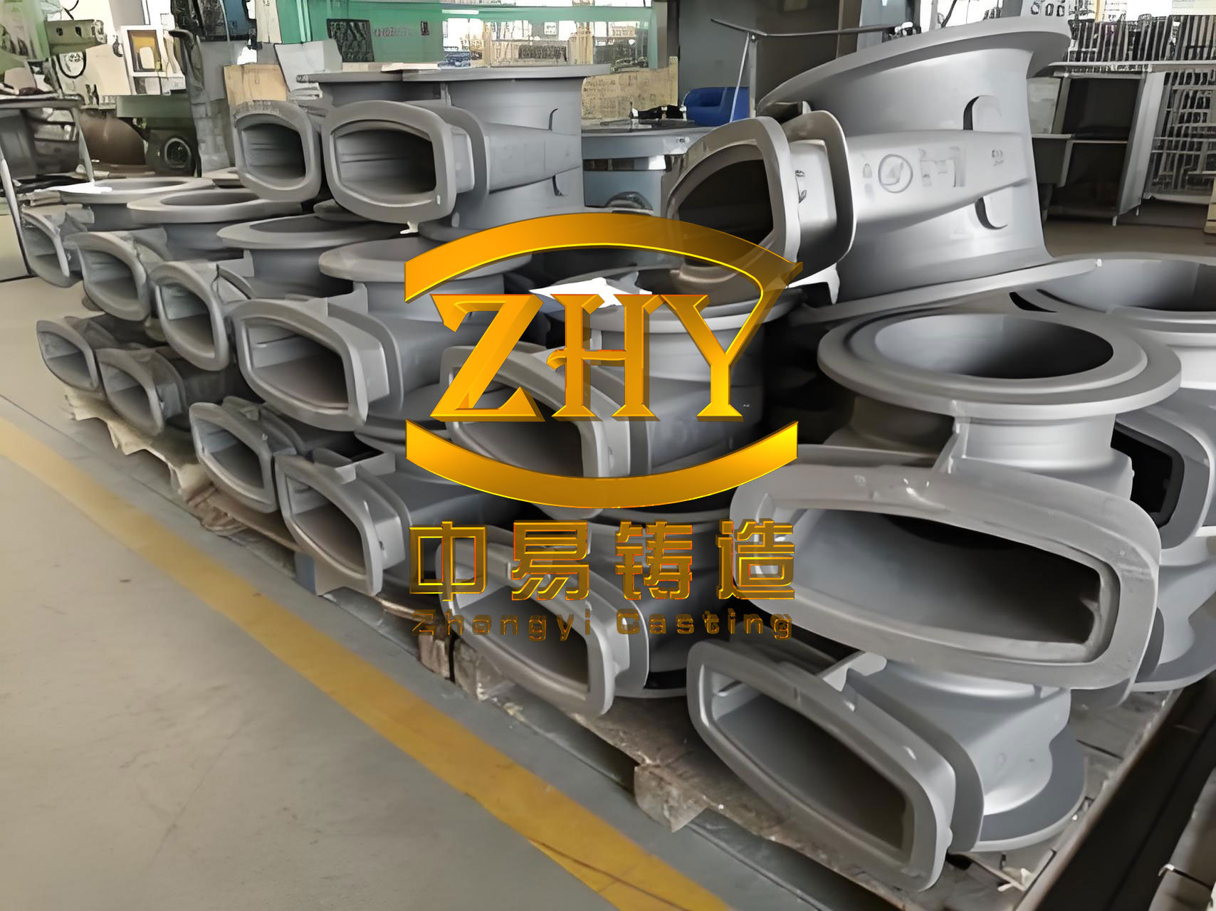
The original setup was a dual-line system for gray iron casting, with core equipment including medium-frequency induction melting furnaces, a semi-automatic pouring machine, a mold-pushing loop, vacuum systems, a sand handling and cooling system, and various dust collectors and auxiliary units. The fundamental objective was to adapt this infrastructure for aluminum, acknowledging that while both are lost foam processes, the equipment and process requirements diverge considerably.
1. Fundamental Process Differences and Driving Factors
The initial gray iron casting line was designed for high-temperature ferrous alloys. The shift to aluminum alloys, with their lower melting point and distinct metallurgical behavior, necessitated a comprehensive re-evaluation of every subsystem. The table below summarizes the core process differences that informed the redesign.
| Parameter/Characteristic | Lost Foam Gray Iron Casting | Lost Foam Aluminum Alloy Casting | Implication for Retrofit |
|---|---|---|---|
| Typical Pouring Temperature | ~1500°C and above | ~760°C | Lower sand cooling demand; different thermal management. |
| Metal Density | High (~7.2 g/cm³) | Low (~2.7 g/cm³) | Different handling dynamics; less thermal mass in sand. |
| Oxidation & Gas Pickup Tendency | Moderate | Very High (especially Hydrogen) | Mandates sophisticated melt purification systems. |
| Pattern Pyrolysis Products | Mostly gaseous, less residue | Significant liquid/viscous EPS residue | Sand reclamation requires contaminant removal (e.g., baking). |
| Shakeout Sand Temperature | High (~300°C+) | Moderate (< 200°C) | |
| Need for Vacuum During Pour | Essential for mold rigidity and filling | Generally not required | Vacuum system can be decommissioned. |
| Typical Melting Equipment | Medium/Coreless Induction Furnace | Reverberatory (Gas) or Low-Pressure Induction Furnace | Fundamental change in melting philosophy. |
These differences formed the basis for our problem analysis and subsequent technical discussions.
2. Analysis and Retrofit of Key Subsystems
2.1 Melting System: Abandoning the Original Gray Iron Casting Approach
The original line utilized two medium-frequency (MF) coreless induction furnaces, standard for gray iron casting. For aluminum, while MF furnaces offer fast melting and low loss for certain alloys, our trials revealed critical shortcomings:
- Gas Pickup (Porosity): The “skin effect” and vigorous electromagnetic stirring in a coreless furnace create a pronounced “hump” or vortex, vigorously drawing air into the melt. This leads to excessive hydrogen pickup, causing unacceptable levels of gas porosity (pinholes) in the final castings, a defect less pronounced in gray iron casting but catastrophic for aluminum integrity. The hydrogen solubility in aluminum follows Sieverts’ law:
$$
C_{H} = K_{H} \sqrt{P_{H_{2}}}
$$
where $C_{H}$ is hydrogen concentration, $K_{H}$ is the equilibrium constant (temperature-dependent), and $P_{H_{2}}$ is the partial pressure of hydrogen at the melt surface. The turbulent surface in an MF furnace increases the effective $P_{H_{2}}$, raising $C_{H}$. - Process Continuity and Thermal Loss: The batch-style melting and tilting-for-transfer operation led to intermittent metal supply and significant temperature drops (often >50°C) before pouring, detrimental to consistency.
- Energy Cost: Electrical melting proved significantly more expensive than gas-fired alternatives for our required throughput.
Following analysis, the decision was made to completely replace the MF furnaces. We selected a dual-chamber, gas-fired reverberatory melting and holding furnace (2 t/hr melting, 4 t holding capacity). This provides a large, calm bath surface, minimizing gas entrainment, ensures continuous metal availability with precise temperature control, and reduces operational energy costs.
2.2 Melt Treatment & Transfer System: An Entirely New Paradigm
This system is unique to quality aluminum casting and had no equivalent in the gray iron casting line. The goal is to reduce hydrogen content and remove inclusions. We evaluated two common industry approaches before designing our system, as detailed below.
| Feature | Option 1: Batch Transfer & Treatment | Option 2: In-Line Continuous Treatment |
|---|---|---|
| Process Flow | Furnace -> Transfer Ladle -> Degassing Unit -> Holding/Pouring Furnace (2nd Degassing) -> Pour | Furnace -> Launder to Holding Furnace (Refining) -> Launder to In-Line Degasser -> Filter Box -> Pouring Furnace/Robot |
| Gas Pickup Risk | High (Multiple open transfers, splash) | Low (Closed or covered launder transfer) |
| Temperature Loss | Very High (~100°C total) | Minimal (Controlled, enclosed flow) |
| Process Stability (Density Index) | Variable, Higher | Consistent, Lower |
| Pouring Efficiency | Low (~4 min/part) | High (Synchronized with line) |
| Metal Yield | Low (Poor tilting furnace accuracy) | High (Robotic pour precision) |
Based on our experience and the need for high integrity and efficiency, we adopted a system resembling Option 2. We procured a system comprising: a rotary degasser in the holding furnace for primary treatment, followed by an in-line rotary degasser for final hydrogen reduction, and a ceramic foam filter box for inclusion removal. The metal is then fed to a temperature-controlled pouring furnace servicing an ABB robotic pouring arm. This enables precise, consistent, and rapid pour sequences critical for high yield.
The effectiveness of degassing can be modeled by the first-order kinetics of hydrogen removal:
$$
\frac{dC}{dt} = -K (C – C_{eq})
$$
where $C$ is the instantaneous hydrogen concentration, $C_{eq}$ is the equilibrium concentration with the purging gas, $K$ is a rate constant dependent on gas bubble surface area and melt dynamics, and $t$ is treatment time. The in-line system provides a controlled, high-$K$ environment for reliable reduction to target $C$.
2.3 Mold Handling & Pouring Loop: Precision is Paramount
The original hydraulic cylinder push system for the flask train, acceptable for gray iron casting, was fundamentally unsuitable for precision aluminum pouring. The main issues were:
- Cumulative Positional Error: Independent flasks with stop-blocks experienced wear. With 38 flasks per line, if each block wore 0.5mm, the total train length could contract by 19mm. Combined with flask deformation and debris, this created unpredictable stopping positions, precluding fixed-point pouring.
- Hydraulic Shock & Vibration: The stop-start action of large hydraulic cylinders induced severe shock through the train, risking distortion of freshly poured, still-solidifying aluminum castings.
The retrofit solution involved a complete mechanical and control overhaul:
- Fixed, Rigid Train: All flasks were permanently linked with pins, creating a continuous, closed-loop train with zero relative movement, eliminating wear-based positional drift.
- Precision Drive: Hydraulic cylinders were replaced by a servo motor-driven dual ball-screw system. This offers superior synchronization, control, and smooth deceleration, eliminating damaging vibration.
- Absolute Positioning: Hydraulic locking pins were installed at key stations (molding, pouring, knockout). After the servo-driven advance, the train is locked precisely in position before any operation (e.g., robotic pour), ensuring repeatability within ±1 mm.
The motion profile of the new system can be described by a smooth S-curve acceleration/deceleration function, minimizing jerk ($j$, the rate of change of acceleration):
$$
a(t) = A_{max} \cdot \left(1 – \cos\left(\frac{2\pi t}{T}\right)\right) / 2 \quad \text{for } 0 \leq t \leq T
$$
where $a(t)$ is acceleration, $A_{max}$ is the target maximum acceleration, and $T$ is the ramp time. This results in a smooth stop with near-zero terminal vibration.
2.4 Sand System: Recalibrating for Lower Thermal Load and Contamination
The change from high-temperature gray iron casting to lower-temperature aluminum casting drastically altered the thermal and contaminant profile of the returned sand.
- Cooling Capacity Oversizing: The original sand cooling system was designed for sand exiting at ~300°C from gray iron casting. With aluminum pouring at ~760°C, return sand temperature fell below 200°C. Over-cooling led to sand temperatures below the optimal range for the process, affecting pattern coating drying and mold stability. We resolved this by removing two of the fluidized-bed cooling units after recalculating the new thermal balance. The simplified heat removal requirement can be expressed as:
$$
\dot{Q}_{remove} = \dot{m}_s \cdot c_{p,s} \cdot (T_{return} – T_{target})
$$
where $\dot{m}_s$ is sand mass flow rate (e.g., 30 t/h), $c_{p,s}$ is sand specific heat (~0.8 kJ/kg·K), $T_{return}$ is ~200°C, and $T_{target}$ is ~50°C. The value of $\dot{Q}_{remove}$ for aluminum is significantly lower than for gray iron casting where $T_{return}$ was >300°C. - Combating Organic Contamination: The lower pyrolysis temperature in aluminum lost foam casting leaves more viscous, tarry EPS residues on the sand grains. This coating reduces sand flowability, hinders compaction, and clogs intergranular spaces needed for gas evacuation, leading to defects like “back-pressure” or poor filling. To solve this, we integrated an intermittent, direct-fired sand baking furnace upstream of the cooler. A portion of the hot return sand is diverted and heated to ~600°C, burning off organic coatings. The key design parameter was the bake rate. Through testing, we determined baking 10% of the total sand flow was sufficient:
$$
\dot{m}_{bake} = f \cdot \dot{m}_s \quad \text{where } f = 0.1
$$
Baking 3 t/h (10% of 30 t/h) restored sand quality without excessive fuel cost. The visual change from black to near-original sand color was a clear indicator of effectiveness.
2.5 Fume Extraction and Environmental Control
The fume composition changed from primarily dust and combustion products in gray iron casting to a stream rich in unburned, sticky hydrocarbons from EPS in aluminum casting. The original baghouse dust collectors were prone to blinding and fire hazards with this new contaminant profile. We replaced them with a 3-stage wet scrubber system. Learning from corrosion failures in a previous installation (carbon steel lasted <1 year), we constructed the scrubber vessel, ducting, and circulating pumps from 304 stainless steel and corrosion-resistant polymers, ensuring long-term reliability in the harsh, acidic environment created by the scrubbing of pyrolysis byproducts.
3. Implementation Results and Conclusions
The retrofit project, utilizing specialized equipment from selected suppliers (e.g., gas furnace, melt purification system, redesigned flask loop, sand baker), has been highly successful. The transformation from a gray iron casting line to a dedicated aluminum line yielded the following key performance indicators:
| Metric | Pre-Retrofit (Gray Iron Casting Line – Idle) | Post-Retrofit (Aluminum Line) |
|---|---|---|
| Primary Product | Gray Iron Castings | Aluminum Castings (e.g., Transmission Housings) |
| Line Cycle Rate | Designed for Iron Pace | 25 Flasks / Hour |
| Overall Equipment Effectiveness (OEE) | N/A (Idle) | > 85% |
| Direct Labor per Line | N/A | 7 Operators |
| Critical Casting Yield | N/A | > 98% Stable |
| Melt Treatment | None (for Gray Iron) | Dual-Stage Degassing + Filtration |
| Sand System Specifics | High-Capacity Cooling, No Cleaning | Right-Sized Cooling + 10% Online Baking |
In summary, retrofitting a lost foam gray iron casting line for aluminum alloy production is a complex but feasible undertaking. It is not a simple reuse but a fundamental re-engineering of key systems: melting, metal treatment, precision handling, and sand reclamation. The core lesson is that the processes, while sharing the “lost foam” name, have distinct metallurgical and physical requirements. Success hinges on recognizing these differences—such as aluminum’s sensitivity to hydrogen versus gray iron’s tolerance, or the different contaminant profiles in the sand—and making decisive, sometimes complete, equipment changes. The outcome is a state-of-the-art aluminum lost foam line that leverages the existing structural framework of the old gray iron casting facility but operates on principles and technologies optimized for the demands of high-integrity, lightweight aluminum casting.