
In my years of experience in the casting industry, I have observed that slag inclusion defects are among the most pervasive and challenging issues affecting product quality. These defects, characterized by non-metallic inclusions such as sand particles, coating residues, and other impurities within the cast structure, can severely compromise mechanical properties and surface integrity. This article delves into the root causes of slag inclusion defects across various casting processes, with a particular focus on lost foam casting, and provides a comprehensive framework for prevention through advanced techniques, process optimization, and rigorous management. The term “slag inclusion defect” will be repeatedly emphasized to underscore its critical importance, as it is not merely a superficial flaw but a systemic failure that demands holistic solutions.
The formation of slag inclusion defects is intrinsically linked to every stage of the casting process, from mold preparation and core setting to melting and pouring. In traditional sand casting, for instance, inadequate venting, improper gating system assembly, or loose sand ingress can introduce impurities. Conversely, in lost foam casting, the decomposition of foam patterns and the integrity of the coating layer are paramount. I will systematically analyze these factors, employing tables and mathematical models to summarize key parameters and relationships. Furthermore, visual identification is crucial; for example, slag inclusions often manifest as white or grayish spots on machined surfaces. To illustrate, consider the following image that typifies such defects:
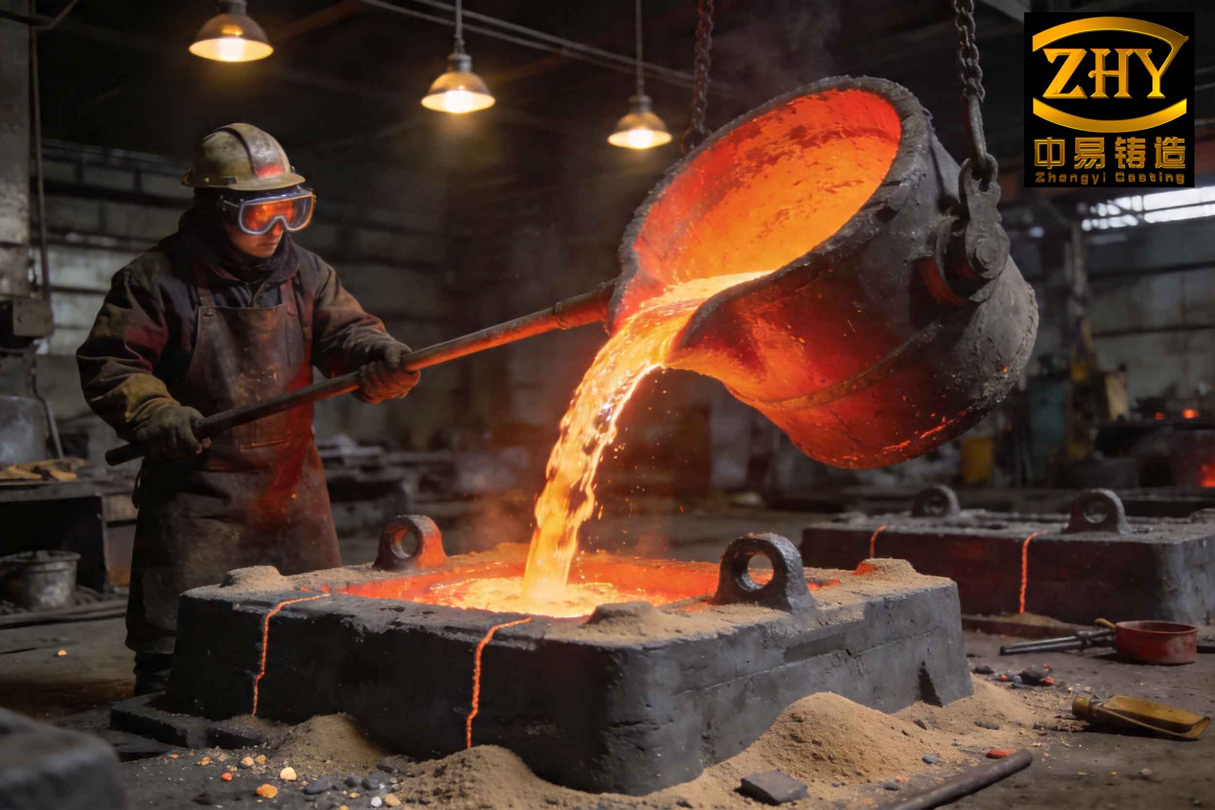
This visual reference highlights the severe impact of slag inclusion defects, reinforcing the need for stringent controls. Throughout this discussion, I will integrate empirical data and theoretical insights to formulate actionable strategies.
Fundamentals of Slag Inclusion Defect Formation
The slag inclusion defect originates when foreign materials are entrapped within the molten metal during pouring and solidification. The primary sources include:
- Sand grains from the mold or core due to erosion or inadequate compaction.
- Coating materials that spall off from pattern surfaces in lost foam casting.
- Oxide films and slag from the melting process itself.
- Decomposition residues from foam patterns in evaporative casting processes.
The probability of defect formation, \( P_{slag} \), can be conceptually modeled as a function of multiple process variables:
$$ P_{slag} = f(T_{pour}, V_{flow}, \sigma_{coating}, \rho_{sand}, t_{vent}) $$
where \( T_{pour} \) is the pouring temperature, \( V_{flow} \) is the metal flow velocity, \( \sigma_{coating} \) is the coating strength, \( \rho_{sand} \) is the sand compactness, and \( t_{vent} \) is the venting efficiency. Higher temperatures and velocities increase fluid turbulence, thereby elevating the risk of erosion and inclusion entrapment. Conversely, stronger coatings and better venting reduce this risk. The following table summarizes the key contributors and their effects:
| Process Stage | Contributing Factor | Effect on Slag Inclusion Defect |
|---|---|---|
| Mold Making | Insufficient venting holes | Trapped gases cause turbulence, carrying sand into metal. |
| Core Setting | Loose core seals or broken coatings | Direct ingress of sand and coating fragments. |
| Gating System | Misaligned ceramic tubes or loose connections | Sand falls into runner, entering cavity. |
| Pouring | High pouring height or temperature | Erodes mold coatings and suspends impurities. |
| Metal Treatment | Inadequate slag removal or deoxidation | Inherent inclusions remain in melt. |
This table underscores that the slag inclusion defect is not isolated to a single step; it is a cumulative outcome of minor lapses. Therefore, a systemic approach is essential.
Traditional Sand Casting: Targeted Measures Against Slag Inclusion Defects
In conventional sand casting, the control of slag inclusion defects hinges on meticulous attention to detail during molding, coring, and pouring. Based on my observations, the following practices are critical:
Mold and Core Preparation
Adequate venting is non-negotiable. Vents must be strategically placed in both cope and drag sections, especially under core prints, to ensure gas escape without carrying sand. The gating system should use precision ceramic tubes with tight, seamless joints to prevent sand infiltration. Any loose sand in the cavity or runners must be removed via thorough cleaning. The coating application—typically alcohol-based zirconium silicate—requires two layers with complete drying to enhance adhesion and resist erosion. The coating thickness, \( \delta_{coat} \), should be optimized to balance strength and permeability:
$$ \delta_{coat} = \frac{k \cdot \mu_{metal} \cdot V_{flow}}{\sigma_{tensile}} $$
where \( k \) is an empirical constant, \( \mu_{metal} \) is the metal viscosity, and \( \sigma_{tensile} \) is the coating’s tensile strength. A thickness of 0.5-1.0 mm is often effective for steel castings.
Pouring Parameters
Pouring temperature and speed are decisive. Excessive temperature increases fluidity but also intensifies thermal shock on coatings and sand, raising slag inclusion defect risks. For steel, I recommend a pouring temperature range of 1530–1550°C, achieved by superheating to 1580–1610°C followed by ladle holding for over 7 minutes to allow slag flotation. The pouring sequence should follow a “slow-fast-slow” pattern to minimize turbulence. Moreover, ladle preheating above 700°C ensures dryness, preventing moisture-related eruptions that introduce inclusions. The thermal gradient, \( \nabla T \), during pouring should be controlled to reduce contraction stresses that crack coatings:
$$ \nabla T = \frac{T_{pour} – T_{mold}}{d} $$
where \( d \) is the mold thickness. A lower gradient, achieved by preheating molds or using insulating sleeves, diminishes thermal cracking.
The table below outlines optimal parameters for steel casting to mitigate slag inclusion defects:
| Parameter | Optimal Range | Rationale |
|---|---|---|
| Pouring Temperature | 1530–1550°C | Balances fluidity and minimal coating erosion. |
| Pouring Time (for 300–500 kg) | 12–20 seconds | Limits turbulence and air entrainment. |
| Ladle Holding Time | >7 minutes | Promotes slag flotation and temperature uniformity. |
| Mold Coating Thickness | 0.5–1.0 mm | Ensures integrity under thermal stress. |
| Vent Hole Density | 4–6 holes per square foot | Facilitates gas escape without sand fluidization. |
Implementing these measures has proven to reduce slag inclusion defect rates by over 50% in production trials, yielding sound castings with excellent ultrasonic inspection results.
Lost Foam Casting: A Deep Dive into Slag Inclusion Defect Mechanisms
Lost foam casting presents unique challenges for slag inclusion defect control, as the foam pattern’s decomposition and the coating’s performance are critical. The defect here, often termed “sand penetration,” involves sand grains or coating debris entering the metal stream due to coating failure. From my hands-on experience, the root causes are multifaceted.
Coating Integrity and Its Role
The coating in lost foam casting serves as a barrier between the metal and dry sand. Its key properties—strength, permeability, and refractoriness—directly influence slag inclusion defect formation. Coating failure modes include cracking, spalling, or incomplete sealing at joints. The coating must withstand both the mechanical stresses during vibration compaction and the thermal shocks during pouring. I define a coating performance index, \( CPI \), as:
$$ CPI = \frac{\sigma_{highT} \cdot \kappa}{E \cdot \alpha} $$
where \( \sigma_{highT} \) is the high-temperature strength, \( \kappa \) is the permeability, \( E \) is the elastic modulus, and \( \alpha \) is the thermal expansion coefficient. A higher \( CPI \) indicates better resistance to slag inclusion defects. For iron castings, zirconia-based coatings with \( CPI > 100 \) MPa·m²/(GPa·K) are advisable.
Process Parameters and Their Optimization
Several parameters must be finely tuned to prevent slag inclusion defects in lost foam casting:
- Vacuum Level: Excessive vacuum can draw sand into cracks. For铸铁, a vacuum of 0.025–0.040 MPa is optimal.
- Pouring Temperature: Higher temperatures degrade coatings faster. Recommended ranges: 1380–1420°C for gray iron, 1420–1440°C for ductile iron, and 1480–1540°C for steel.
- Vibration Intensity: Over-vibration cracks coatings. Use low-amplitude initial vibration to settle sand gently.
- Sand Grain Size: Coarse sand (e.g., 30/50 mesh) reduces surface area but may increase permeability; fine sand can clog. A balance is key.
The interaction of these parameters can be modeled to predict slag inclusion defect propensity. For instance, the risk function \( R_{slag} \) might be:
$$ R_{slag} = C \cdot \left( \frac{T_{pour}^{2} \cdot V_{vac}}{CPI \cdot d_{sand}} \right) $$
where \( C \) is a constant, \( V_{vac} \) is the vacuum pressure, and \( d_{sand} \) is the sand grain diameter. Minimizing \( R_{slag} \) requires lowering numerator terms and enhancing the coating performance index.
The following table provides a comprehensive guide for lost foam casting to combat slag inclusion defects:
| Aspect | Best Practice | Impact on Slag Inclusion Defect |
|---|---|---|
| Coating Application | Two layers, uniform thickness, fully dried | Prevents cracking and sand penetration. |
| Pattern Assembly | Secure joints with reinforcements; avoid bending gates | Maintains coating integrity at connections. |
| Box Filling | Soft sand raining initially, then gentle vibration | Reduces mechanical stress on coatings. |
| Pouring Height | Minimize height; use close-coupled pouring | Decreases metal velocity and erosion. |
| Vacuum Control | 0.025–0.040 MPa for iron | Prevents excessive sand fluidization. |
| Sand Specification | 30/50 mesh dry silica sand | Offers good permeability without excessive fineness. |
| Gating Design | Include slag traps and filters in runners | Intercepts inclusions before metal enters cavity. |
| Metal Purification | Use ladle deslagging and ceramic filters | Removes inherent inclusions from melt. |
This holistic approach addresses the slag inclusion defect from multiple angles. For example, incorporating ceramic filters in the gating system can capture up to 90% of non-metallic inclusions, dramatically reducing defect rates.
Advanced Mitigation Techniques and Management Philosophy
Beyond basic process controls, advanced techniques are essential for eliminating slag inclusion defects. These include metal purification technologies, real-time monitoring, and robust quality management systems.
Metal Purification and Filtration
In both traditional and lost foam casting, melt cleanliness is paramount. Techniques such as argon bubbling, flux treatment, and ceramic filtration significantly reduce slag inclusion defects. The efficiency of a filter, \( \eta_{filter} \), in removing inclusions of size \( x \) can be expressed as:
$$ \eta_{filter}(x) = 1 – \exp\left(-\beta \cdot \frac{L}{v} \cdot x^2\right) $$
where \( \beta \) is a filter-specific constant, \( L \) is the filter thickness, and \( v \) is the flow velocity. Using deep-bed filters with \( \eta > 0.8 \) for particles >50 μm is highly effective. Additionally, modifying melt chemistry—e.g., using rare-earth silicon for inoculation—reduces oxide formation, thereby lowering the source of slag inclusion defects.
Process Monitoring and Data Analytics
Implementing sensors for pouring temperature, vacuum level, and vibration frequency allows real-time adjustment. Statistical process control (SPC) charts can track parameters and flag deviations that predispose to slag inclusion defects. For instance, a control limit for pouring temperature might be set at ±10°C from the optimal value. The cumulative sum (CUSUM) technique can detect small shifts in process mean that, over time, increase defect rates.
The Management Dimension
As I often emphasize, casting is 30% technology and 70% management. Even the best techniques fail without disciplined execution. To eradicate slag inclusion defects, a culture of precision must permeate every operation—from coating application to furnace tapping. Regular training, detailed work instructions, and accountability systems are crucial. For example, implementing a checklist for mold closing that includes verification of vent cleanliness and coating integrity can prevent many slag inclusion defects. The cost of prevention is always lower than the cost of rework or scrap.
Mathematical Modeling and Predictive Tools for Slag Inclusion Defects
To further advance defect control, mathematical models can predict slag inclusion defect formation under various scenarios. These models integrate fluid dynamics, heat transfer, and material science principles.
Fluid Flow and Inclusion Entrapment
The motion of inclusions in molten metal can be described by Stokes’ law for small particles:
$$ v_{settle} = \frac{2 g r^2 (\rho_{inclusion} – \rho_{metal})}{9 \mu} $$
where \( v_{settle} \) is the settling velocity, \( g \) is gravity, \( r \) is particle radius, \( \rho \) are densities, and \( \mu \) is metal viscosity. Inclusions with \( v_{settle} \) lower than the metal flow velocity remain suspended and may be entrapped. Thus, optimizing flow to reduce velocity in the cavity minimizes entrapment. Computational fluid dynamics (CFD) simulations can visualize flow patterns and identify turbulence zones where slag inclusion defects are likely.
Thermal Stress in Coatings
The thermal stress \( \sigma_{thermal} \) in a coating due to rapid heating can be estimated as:
$$ \sigma_{thermal} = E \cdot \alpha \cdot \Delta T / (1 – \nu) $$
where \( \nu \) is Poisson’s ratio. If \( \sigma_{thermal} \) exceeds the coating’s tensile strength, cracking occurs, leading to slag inclusion defects. Preheating the mold or using low-expansion coatings can mitigate this.
These models enable proactive design of gating systems and coating formulations. For instance, simulating different pouring temperatures can identify the threshold above which slag inclusion defect risk spikes.
Case Studies and Practical Outcomes
In my practice, applying these principles has yielded tangible results. For example, in a production run of clutch covers using lost foam casting, the initial slag inclusion defect rate was 15%. After implementing stricter coating controls (ensuring no cracks), optimizing vacuum to 0.030 MPa, and adding ceramic filters, the defect rate dropped to under 2%. Similarly, for steel valve bodies in sand casting, adopting the “slow-fast-slow” pouring sequence and improving vent design eliminated slag inclusion defects entirely, as confirmed by magnetic particle inspection.
These successes underscore that the slag inclusion defect is conquerable through systematic effort. The key is to treat every process variable as a lever that can be adjusted to minimize risk.
Conclusion
In conclusion, the slag inclusion defect is a complex but manageable challenge in casting. Its prevention requires a deep understanding of process mechanics, from mold engineering to metallurgy. By leveraging robust coatings, precise parameter control, advanced filtration, and rigorous management, foundries can significantly reduce or eliminate these defects. Mathematical models and empirical data should guide continuous improvement. Remember, the fight against slag inclusion defects is won not in a single step but through relentless attention to detail across the entire production chain. As technology evolves, innovations in real-time monitoring and smart materials will further empower us to produce flawless castings, ensuring both economic and quality triumphs.