
In my experience with ductile iron casting, small ductile iron casting is one of the most difficult categories to produce without internal and external shrinkage defects. A small ductile iron casting usually has a thin wall, a small casting modulus, and a low process yield. These characteristics make it very difficult to use graphitic expansion for self-feeding. When self-feeding fails, shrinkage porosity and sink marks appear. I have repeatedly observed that these defects are not simply the result of a poor feeder or a missing chill. They are closely related to the solidification mode of ductile iron, the solidification temperature range, the temperature gradient inside the mold cavity, and the silicon content of the liquid iron. In the following sections, I explain the mechanisms that control shrinkage porosity and sink formation in small ductile iron casting and present practical measures that I have found effective. The main measures are reasonable control of silicon content and the use of a special nodularizer, namely a pure lanthanum nodularizer, to delay early graphite precipitation and to maximize the beneficial expansion of late graphite precipitation.
Defect terminology and basic observations
Shrinkage porosity in ductile iron casting is a dispersed, fine, and often interdendritic or intergranular void. It can be macroscopic, meaning visible to the naked eye, or microscopic, meaning visible only under a microscope. Sink, also called a sink mark or depression, is a surface depression that forms when a solid shell surrounds a region of liquid or partially solidified metal. If a local vacuum develops inside the shell and the shell strength is insufficient at high temperature, the shell collapses under atmospheric pressure. The resulting surface depression replicates the mold wall surface, so it can be distinguished from a gas pit or a surface blowhole. Sink marks are usually located on thick cross sections, structural hot spots, or the surfaces of heavy sections. Depending on the pouring position, they can appear on the bottom, side, or top surface of a small ductile iron casting.
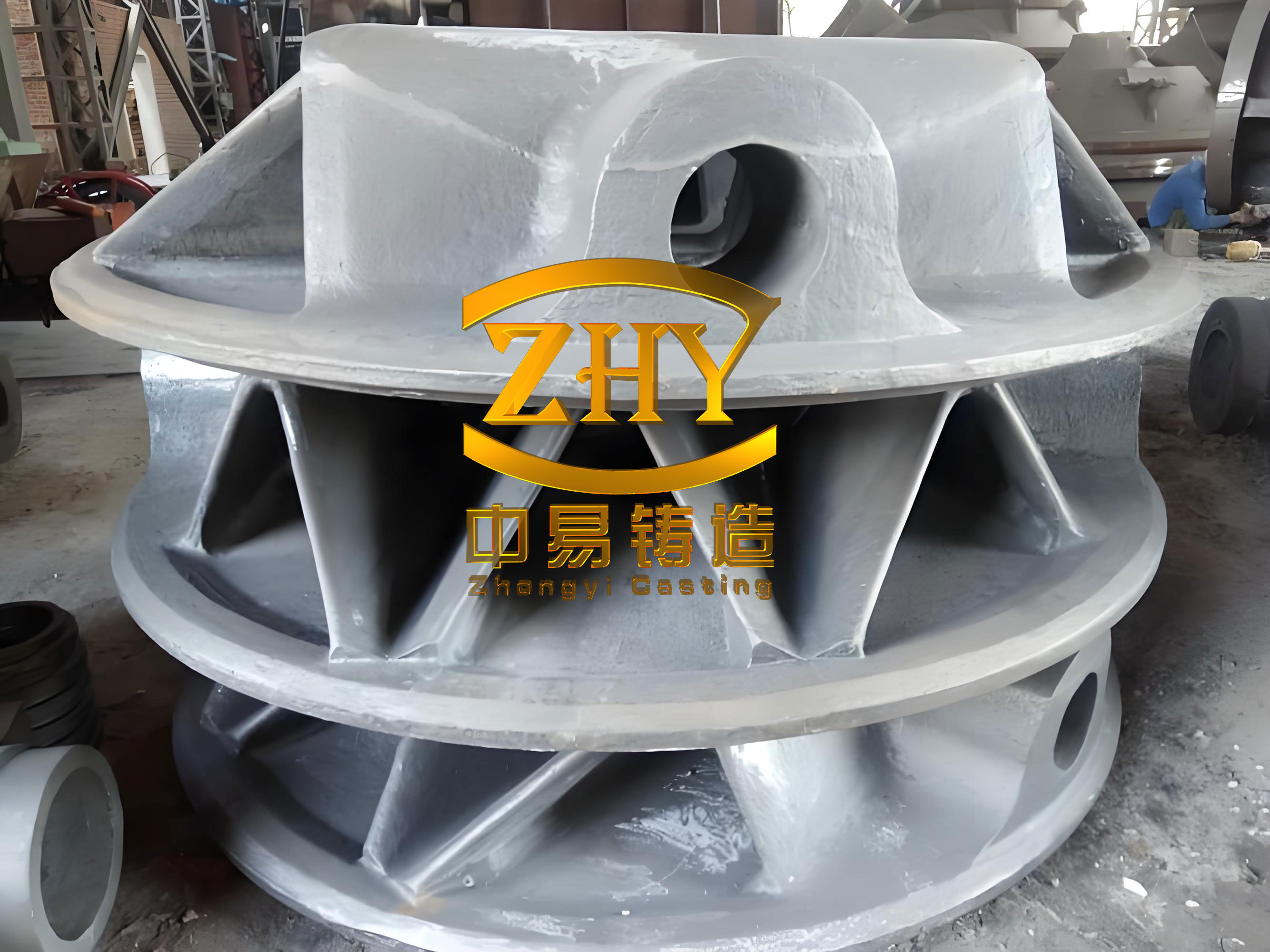
Solidification mode and its effect on defect type
Ductile iron normally solidifies in a mushy or paste-like mode. Graphite nodules grow inside austenite shells, and this divorced eutectic growth restricts carbon diffusion. The growth rate is slow, and the formation of a strong, continuous outer shell is delayed. When the liquid metal in the mold cavity forms a closed solid shell, and when a local vacuum space appears inside that shell, the high-temperature shell may not have enough strength to resist atmospheric pressure. The shell then caves inward, producing a sink. Shrinkage porosity forms when liquid and solidification contraction create dispersed voids that cannot be fed by external liquid metal.
In contrast, a skin-forming or layer-by-layer solidification mode produces a narrow solidification range and a strong shell early in solidification. This mode tends to form concentrated shrinkage cavities, often called pipe or macro-shrinkage, rather than dispersed porosity. The difference is important because a small ductile iron casting that suffers from shrinkage porosity and sink does not usually benefit from simply adding a large feeder. The defect mechanism is not the same as that of a concentrated shrink hole.
| Aspect | Skin-forming solidification | Mushy solidification |
|---|---|---|
| Solidification range | Narrow | Wide |
| Shell formation | Early and strong | Late and weak |
| Feeding path | Short and direct | Long and blocked by mushy zone |
| Typical defect | Concentrated shrink hole | Shrinkage porosity and sink |
| Self-feeding potential | Low for late liquid | High only if late graphite expansion is sufficient |
| Effect of wide range | Not applicable | Increases porosity and sink tendency |
The solidification temperature range can be expressed as:
$$ \Delta T_s = T_L – T_S $$
where \(T_L\) is the liquidus temperature and \(T_S\) is the solidus temperature. The temperature gradient in the casting can be written as:
$$ G = \frac{\Delta T}{\Delta x} $$
The width of the mushy zone is then approximately:
$$ w = \frac{\Delta T_s}{G} $$
A wider mushy zone means that liquid and solid coexist over a larger volume for a longer time. Early graphite precipitation occurs while feeding channels are still open, so the expansion caused by that early graphite does not compensate for later contraction. The expansion is effectively lost to the riser or gating system. Moreover, if early graphite precipitation consumes a large fraction of the carbon available for graphite growth, less graphite forms in the late stage of solidification. The late stage is precisely when the casting needs expansion the most, because isolated liquid pockets can no longer be fed by external liquid. Therefore, a wide solidification range increases the tendency for shrinkage porosity and sink in small ductile iron casting.
Modulus, solidification time, and self-feeding
The casting modulus is defined as:
$$ M = \frac{V}{A} $$
where \(V\) is the volume and \(A\) is the heat-dissipating surface area. For a small ductile iron casting, the modulus is small. According to Chvorinov’s rule, the solidification time is approximately:
$$ t_f = B M^2 $$
where \(B\) is a mold constant. A small modulus means a short solidification time. The time available for feeding is short, and the time available for late graphite expansion to act is also short. In a small ductile iron casting, the temperature gradient is often small because the section thickness is thin and heat is extracted relatively uniformly. A small temperature gradient produces a wide mushy zone, which further increases the risk of shrinkage porosity and sink.
The condition for effective self-feeding can be expressed in a simplified form as:
$$ V_{net} = V_{graphite} – V_{liquid\ contraction} – V_{solidification\ contraction} $$
For a small ductile iron casting to avoid shrinkage defects, the net volume change must be zero or positive during the final stage of solidification:
$$ V_{net} \ge 0 $$
However, this condition is only useful if the graphite expansion occurs late enough. If graphite expansion occurs early, it is not contained within the casting. A more precise condition is:
$$ V_{g,late} \ge V_{liq,contr} + V_{sol,contr} $$
where \(V_{g,late}\) is the volume expansion from late graphite precipitation. This is the core challenge in small ductile iron casting: how to delay graphite precipitation so that expansion occurs after the feeding paths are closed, but before the remaining liquid pockets are completely isolated and unable to transmit pressure.
Influence of solidification range on shrinkage porosity and sink
If the solidification temperature range is wide, graphite precipitation begins over a wide temperature interval. Early graphite nodules form while a significant amount of liquid is still present and while the gating system or feeder neck is still open. The expansion produced by these early nodules pushes liquid back into the gating system instead of compensating for contraction in the casting. By the time the casting becomes isolated, much of the graphite-forming potential has already been consumed. The remaining liquid has a lower carbon equivalent and a lower graphite expansion capacity. As a result, shrinkage porosity and sink become more likely.
I often use a simplified defect tendency index to compare different conditions in small ductile iron casting:
$$ D_{shrink} = \frac{\Delta T_s}{G} \cdot \frac{1}{f_{g,late}} $$
In this expression, \(D_{shrink}\) increases when the solidification range \(\Delta T_s\) is large, when the temperature gradient \(G\) is small, and when the late graphite fraction \(f_{g,late}\) is small. A high \(D_{shrink}\) indicates a high tendency for shrinkage porosity and sink. This index is not a precise physical law, but it helps me organize the variables when I troubleshoot a small ductile iron casting.
| Solidification range | Mushy zone width | Early graphite fraction | Late graphite fraction | Defect tendency |
|---|---|---|---|---|
| Narrow | Small | Low | High | Low shrinkage porosity and sink |
| Moderate | Medium | Moderate | Moderate | Moderate risk |
| Wide | Large | High | Low | High shrinkage porosity and sink |
Silicon as a key variable
Silicon is one of the most important elements affecting the solidification range of ductile iron. Pure iron-carbon alloy undergoes eutectic solidification at a constant temperature, approximately 1155 °C. In real cast iron, alloying elements, especially silicon, cause eutectic solidification to occur over a temperature range. Silicon increases the solidification range. Silicon also increases the activity of carbon, so it promotes early graphite precipitation. Therefore, a higher silicon content in ductile iron casting increases the amount of graphite that forms early, reduces the amount of graphite that forms late, and increases the tendency for shrinkage porosity and sink.
The carbon equivalent is often calculated as:
$$ CE = C + \frac{Si}{3} + \frac{P}{3} $$
For ductile iron casting, the eutectic solidification range can be approximated as:
$$ \Delta T_E = \Delta T_0 + k_{Si} Si + \sum k_i X_i $$
where \(\Delta T_0\) is the base range for a reference composition, \(k_{Si}\) is a positive coefficient for silicon, and \(k_i\) are coefficients for other elements. Because \(k_{Si}\) is positive, increasing silicon always widens the eutectic solidification range. The carbon activity can be expressed qualitatively as:
$$ a_C = f(C, Si, Mn, P, S) $$
Increases in silicon raise \(a_C\), which promotes early graphite nucleation and growth. This is beneficial for avoiding chill and for increasing ferrite content, but it is harmful for shrinkage resistance in small ductile iron casting.
| Silicon content | Solidification range | Early graphite | Late graphite | Shrinkage risk |
|---|---|---|---|---|
| Low, e.g. 2.1–2.4% | Narrow | Low | Higher | Lower, but chill risk may increase |
| Moderate, e.g. 2.5–2.8% | Controlled | Moderate | Moderate to high | Acceptable for many small ductile iron casting |
| High, e.g. 2.9–3.2% | Wide | High | Low | High |
| Excessive, above 3.2% | Very wide | Very high | Very low | Very high |
In my practice, I have found that many foundries increase silicon to 2.9–3.2% when producing low-grade, thin-wall small ductile iron casting. The intention is to avoid white iron and to ensure elongation. However, this practice widens the eutectic solidification range and increases early graphite precipitation. The result is a greater tendency for shrinkage porosity and sink. When the casting geometry and process do not allow effective feeders or chills, especially in shell molding with iron shot backing or in vertical clay sand lines, silicon control becomes one of the few practical solutions. I recommend that for small ductile iron casting with medium to thin walls, the silicon content should be controlled in the range of 2.5% to 2.8% to reduce the risk of shrinkage porosity and sink.
Carbon and silicon balance
Carbon provides the graphite expansion that can offset contraction. Silicon controls the timing of that expansion. Therefore, I prefer to keep the carbon equivalent at a suitable level while using the highest practical carbon content and the lowest practical silicon content. A useful starting point for small ductile iron casting is:
$$ CE_{target} = 4.2\% \text{ to } 4.5\% $$
$$ Si_{target} = 2.5\% \text{ to } 2.8\% $$
$$ C_{target} = CE_{target} – \frac{Si_{target}}{3} $$
For example, if \(CE_{target} = 4.4\%\) and \(Si_{target} = 2.7\%\), then:
$$ C_{target} = 4.4 – \frac{2.7}{3} = 4.4 – 0.9 = 3.5\% $$
In many small ductile iron casting applications, carbon can be increased to 3.6–3.8% while silicon is reduced to 2.5–2.8%. This combination increases late graphite expansion and reduces the solidification range. I have seen this approach eliminate shrinkage porosity in shell-molded small ductile iron casting without adding feeders or chills.
| Parameter | Typical high-Si practice | Recommended low-Si practice |
|---|---|---|
| Carbon, % | 3.4–3.6 | 3.6–3.8 |
| Silicon, % | 2.9–3.2 | 2.5–2.8 |
| Carbon equivalent, % | 4.4–4.7 | 4.2–4.5 |
| Solidification range | Wide | Narrower |
| Early graphite | High | Lower |
| Late graphite | Low | Higher |
| Shrinkage tendency | High | Lower |
Graphite expansion and the importance of timing
The volume change associated with graphite precipitation can be expressed as:
$$ \Delta V_g = \frac{\rho_{liquid} – \rho_{graphite}}{\rho_{graphite}} f_g $$
where \(f_g\) is the fraction of graphite formed. Because graphite has a lower density than liquid iron, graphite precipitation produces a positive volume change. However, this positive volume change is only useful for feeding if it occurs in a region that is isolated from the gating system and if the surrounding shell can contain the pressure. The fraction of useful late graphite can be written as:
$$ f_{g,late} = f_g – f_{g,early} $$
The ratio of late to early graphite is a useful indicator:
$$ R = \frac{f_{g,late}}{f_{g,early}} $$
For shrinkage resistance, I want \(R\) to be as high as possible. A high \(R\) means that graphite expansion is delayed until the late stage of solidification. In small ductile iron casting, a high \(R\) helps compensate for liquid and solidification contraction in isolated hot spots. A low \(R\) means that most graphite forms early, and the late liquid contracts without sufficient expansion. This is why I focus on delaying graphite precipitation rather than simply increasing total graphite nodule count.
| Graphite precipitation stage | Effect on feeding | Effect on shrinkage | Desired condition |
|---|---|---|---|
| Early, before isolation | Expansion pushes liquid back to feeder or gating system | Wastes expansion potential | Minimize |
| Intermediate | Partially useful, but feeding paths may still be open | Moderate effect | Control |
| Late, after isolation | Compensates contraction in isolated liquid pockets | Reduces porosity and sink | Maximize |
Pure lanthanum nodularizer and delayed graphite precipitation
I have found that the choice of rare earth element in the nodularizer has a significant effect on graphite precipitation timing and on shrinkage defects in small ductile iron casting. A pure lanthanum nodularizer, typically a lanthanum-bearing magnesium ferrosilicon alloy or a lanthanum cored wire, delays graphite precipitation during the early stage of eutectic solidification. As a result, more graphite forms in the late stage. This late graphite expansion can compensate for contraction in the final solidifying regions.
When I compare microstructures from a lanthanum-treated ductile iron casting with those from a cerium-treated ductile iron casting, the difference is clear. Lanthanum treatment produces a bimodal or broad graphite size distribution: many very small graphite nodules and a small number of larger nodules. The small nodules usually form in the last regions to solidify. Their expansion counteracts shrinkage and helps prevent porosity and sink. Cerium treatment, especially with excessive inoculation or bismuth addition, often produces a uniform distribution of many early graphite nodules. Although such a microstructure may appear visually appealing, it can increase the shrinkage tendency because most graphite forms early and the late expansion is insufficient.
A simple empirical expression for shrinkage tendency as a function of nodule characteristics is:
$$ S = S_0 + \alpha N_{early} – \beta \sigma_d – \gamma f_{g,late} $$
Here, \(S\) is the shrinkage tendency, \(N_{early}\) is the number of early graphite nodules, \(\sigma_d\) is the width of the nodule size distribution, and \(f_{g,late}\) is the late graphite fraction. The coefficients \(\alpha\), \(\beta\), and \(\gamma\) are positive. This expression shows that increasing early nodule count raises shrinkage tendency, while increasing the size distribution width and the late graphite fraction lowers shrinkage tendency. A pure lanthanum nodularizer increases \(\sigma_d\) and \(f_{g,late}\), so it reduces \(S\). A pure cerium nodularizer or excessive inoculation tends to increase \(N_{early}\) and reduce \(\sigma_d\), so it increases \(S\).
| Nodularizer type | Early graphite | Late graphite | Graphite size distribution | Shrinkage tendency |
|---|---|---|---|---|
| Pure lanthanum | Low | High | Broad, bimodal | Low |
| Pure cerium | High | Low | Uniform, narrow | High |
| Mixed rare earth | Moderate | Moderate | Moderate | Moderate |
| Excessive inoculation | Very high | Very low | Very uniform | Very high |
In my experience, the use of a pure lanthanum nodularizer is particularly valuable when process measures such as feeders and chills are difficult to apply. For small ductile iron casting produced in shell molds with iron shot backing, or in vertical clay sand lines, the ability to delay graphite precipitation can be the difference between success and failure. I have used lanthanum cored wire in production and observed a clear reduction in shrinkage porosity and sink. The treatment should be controlled so that the lanthanum addition is sufficient to modify graphite precipitation without causing other problems such as slag or excessive rare earth residuals.
Inoculation, nodule count, and misconceptions
Many foundry engineers believe that increasing the graphite nodule count will always reduce shrinkage in ductile iron casting. In my experience, this is not true. A higher nodule count can reduce shrinkage only if the nodule size distribution is sufficiently broad. If inoculation is excessive, or if bismuth is used to increase nodule count, the result is often a large number of small, uniformly sized early graphite nodules. These nodules form early, when feeding channels are still open, so their expansion is not useful for compensating late contraction. The late liquid then has less carbon available for graphite growth, and shrinkage porosity or sink becomes more likely.
I use the following qualitative rule: it is not the total number of graphite nodules that matters most; it is the timing and size distribution of those nodules. A desirable microstructure for a small ductile iron casting contains a broad distribution with some very small nodules that form late. These late-forming nodules provide expansion exactly where it is needed. Therefore, I avoid over-inoculation and avoid unnecessary bismuth additions when the goal is to reduce shrinkage defects.
| Practice | Effect on nodule count | Effect on size distribution | Effect on late graphite | Effect on shrinkage |
|---|---|---|---|---|
| Moderate inoculation | Moderate increase | Broadens | Increases | Reduces |
| Excessive inoculation | Large increase | Narrows | Decreases | Increases |
| Bismuth addition | Large increase | Narrows | Decreases | Increases |
| Pure lanthanum nodularizer | Moderate increase | Broadens | Increases | Reduces |
Practical case: silicon reduction in a shell-molded small ductile iron casting
I have worked with a foundry that produces a small ductile iron casting with a nominal grade equivalent to a low-alloy ferritic ductile iron. The casting was made in a shell mold with iron shot backing. The wall thickness was thin, and the modulus was small. The original composition had a relatively high silicon content, approximately 3.1%, and a carbon content of approximately 3.4%. The carbon equivalent was high, but the solidification range was wide. Shrinkage porosity appeared in the hot spot region and near the ingate. Feeders and chills were difficult to apply because of the mold design and the small casting size.
I recommended reducing the final silicon content to approximately 2.7% and increasing the carbon content to approximately 3.7%. The carbon equivalent was kept within a suitable range. No other major process changes were made. After this adjustment, the shrinkage porosity disappeared. The microstructure still had sufficient ferrite, and the mechanical properties remained acceptable. This case illustrates that in a small ductile iron casting, silicon reduction can be more effective than simply adding more feeding.
| Parameter | Before adjustment | After adjustment |
|---|---|---|
| Carbon, % | 3.4 | 3.7 |
| Silicon, % | 3.1 | 2.7 |
| Carbon equivalent, % |