
In the manufacturing of critical components for wind turbine generators, I have encountered a persistent challenge related to porosity in casting, specifically in high-toughness ductile iron housing castings. These castings, such as the lower housing, are essential for the gearbox assembly, where they endure significant torsional loads and must exhibit high strength, toughness, and resistance to low-temperature brittleness. However, porosity in casting has led to oil leakage issues, resulting in the scrapping of over 100 out of more than 1,000 produced castings. This porosity in casting, primarily caused by inadequate venting of resin-bonded sand cores, has driven our efforts to analyze and refine the casting process. Through first-hand experience, we have identified key factors contributing to porosity in casting and implemented effective solutions, significantly improving product quality and reducing costs.
The housing casting in question has external dimensions of 645 mm × 435 mm × 645 mm, with a rough weight of 450 kg and a main wall thickness of 35 mm. It is made of ductile iron grade QT400-18AL, which requires precise chemical composition to achieve the desired mechanical properties. The nominal chemical composition is summarized in Table 1 below. This composition is critical for minimizing porosity in casting, as elements like sulfur and phosphorus can exacerbate gas formation.
| Element | Range |
|---|---|
| Carbon (C) | 3.75–3.80 |
| Silicon (Si) | 1.90–2.10 |
| Manganese (Mn) | ≤ 0.20 |
| Phosphorus (P) | ≤ 0.020 |
| Sulfur (S) | ≤ 0.015 |
| Magnesium (Mg) | 0.03–0.05 |
| Rare Earth (RE) | 0.003–0.005 |
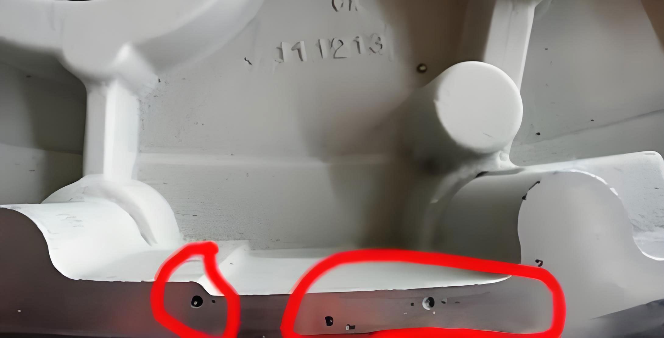
Our initial casting process utilized a furan resin sand molding system, with resin added at 1.1–1.3% of sand weight and a curing agent at 50% of resin weight. The gating system was designed as a bottom-pouring arrangement with one sprue, allowing molten iron to enter the cavity through the mating surfaces of the upper and lower housings. Three bottle-shaped risers, each Φ140 mm, were placed at the top edges, along with a sprue of Φ70 mm, runners of 60 mm × 80 mm × 100 mm, and 12 ingates of 40 mm × 44 mm × 10 mm. Melting was conducted in a 15-ton medium-frequency induction furnace to ensure high-quality iron, with rapid analysis for composition adjustment. Despite these measures, porosity in casting remained a prevalent defect, often visible after shot blasting as surface pores that could penetrate the wall thickness, leading to oil leakage and rejection.
To understand the root causes of porosity in casting, we conducted a detailed analysis of the casting technology. Resin-bonded sand is known for its high gas evolution during pouring, which must be efficiently vented to prevent gas entrapment. The original process, as illustrated in the schematic, lacked adequate venting mechanisms. The sand cores, particularly the core #1, were fully surrounded by molten iron, making gas escape difficult. Although six vent holes were set on the upper mold plane, they proved insufficient due to blocked pathways. We formulated a simple model to describe gas generation and venting, where the total gas volume produced, $$ G $$, can be expressed as:
$$ G = \int_{0}^{t} g(T) \cdot V_s \, dt $$
Here, $$ g(T) $$ is the gas evolution rate per unit volume of sand, which depends on temperature $$ T $$, and $$ V_s $$ is the volume of the sand core. For resin sand, $$ g(T) $$ increases rapidly above certain temperatures, contributing to porosity in casting if not vented. The venting resistance, $$ R_v $$, can be approximated by:
$$ R_v = \frac{L}{\kappa \cdot A} $$
where $$ L $$ is the vent path length, $$ \kappa $$ is the permeability of the sand, and $$ A $$ is the cross-sectional area of vents. In our case, high $$ R_v $$ due to long paths and small $$ A $$ led to gas accumulation. Additionally, factors like improper coating application and excessive curing agent exacerbated gas evolution. For instance, the gas evolution from the resin sand can be estimated using an empirical relation: $$ G_{resin} = k_r \cdot m_{resin} \cdot e^{-\frac{E_a}{RT}} $$, where $$ k_r $$ is a constant, $$ m_{resin} $$ is the resin mass, $$ E_a $$ is activation energy, $$ R $$ is the gas constant, and $$ T $$ is temperature. This highlights how process variations directly influence porosity in casting.
Our investigation revealed several operational issues. First, the core #1 was not equipped with any venting devices during molding, and the process documentation did not specify such requirements. Workers avoided adding vents due to fears of leakage, but this trapped gas within the core. During pouring, the buoyant force from the molten iron caused core #1 to shift slightly upward, creating gaps at the core prints that allowed iron infiltration, further blocking venting paths. As a result, gas from the core entered the mold cavity, causing turbulent flow and leaving pores upon solidification. Second, the coating process for core #1 was inconsistent; workers often applied the entire coating before ignition, allowing alcohol to penetrate and increase gas evolution. Third, workers sometimes私自 increased the curing agent ratio to speed up production, unaware that this raised gas evolution and intensified porosity in casting. We quantified this effect by measuring gas volumes under different curing agent ratios, as shown in Table 2.
| Curing Agent Ratio (% of resin) | Gas Evolution Volume (mL/g sand) | Impact on Porosity in Casting |
|---|---|---|
| 40 | 15.2 | Low |
| 50 (Standard) | 18.7 | Moderate |
| 60 | 22.5 | High |
| 70 | 25.8 | Severe |
To eliminate porosity in casting, we implemented a series of corrective measures focused on enhancing venting and process control. The most critical change was modifying core #1 by integrating a venting system. We designed a “#”-shaped骨架 within the core, around which two vent ropes were wound and connected to vent pipes leading out of the lower mold. To prevent molten iron leakage, the vent holes were sealed with resin sand after core assembly, and the lower mold was elevated with chills to facilitate gas escape. Additionally, the fastening bolts for core #1 were increased from Φ10 mm to Φ16 mm to minimize upward movement. This redesign ensured that vent paths remained open throughout pouring, reducing gas entrapment and mitigating porosity in casting. The venting efficiency can be described by the improved flow equation: $$ Q_v = \frac{\Delta P}{R_v} $$, where $$ Q_v $$ is the venting flow rate and $$ \Delta P $$ is the pressure difference; with more vents, $$ R_v $$ decreases, increasing $$ Q_v $$ and reducing porosity in casting.
Second, we standardized the coating application process for core #1. The procedure now requires coating half of the core at a time, followed by surface drying with a gas torch, and repeating for the other half. After full coating, a final drying step is mandated to eliminate residual moisture and alcohol, which lowers gas evolution. This reduces the risk of porosity in casting by minimizing additional gas sources. Third, we enforced strict adherence to the curing agent ratio, setting it at 50% of resin weight without deviations. Regular audits were introduced to ensure compliance, as even small increases can significantly elevate gas evolution, as per the formula: $$ \Delta G = \alpha \cdot \Delta c $$, where $$ \Delta G $$ is the change in gas volume, $$ \alpha $$ is a proportionality constant, and $$ \Delta c $$ is the change in curing agent concentration. By controlling these variables, we tackled the root causes of porosity in casting.
The effectiveness of these measures was evident in the subsequent production batches. We compared the rejection rates due to porosity in casting over four months before and after implementation, as summarized in Table 3. The data show a dramatic decline in defects, with the rejection rate dropping to as low as 2.14% within two months of improvements. This not only enhanced product quality but also yielded substantial cost savings, estimated at over 150,000 monetary units from reduced scrap.
| Period | Total Production (pieces) | Rejected Pieces Due to Porosity in Casting | Rejection Rate (%) |
|---|---|---|---|
| Before: Month 1 | 120 | 13 | 10.83 |
| Before: Month 2 | 120 | 12 | 10.00 |
| After: Month 1 | 140 | 4 | 2.85 |
| After: Month 2 | 140 | 3 | 2.14 |
In reflection, our experience underscores that porosity in casting, particularly in resin sand processes for wind turbine components, is largely preventable through diligent venting design and process discipline. The high gas evolution of resin sand necessitates robust排气 systems, such as the “#”-shaped venting骨架 we adopted, which ensures continuous gas escape during and after mold filling. Moreover, strict adherence to coating protocols and curing agent ratios plays a pivotal role in minimizing gas sources. From a broader perspective, porosity in casting can be modeled and controlled using principles of fluid dynamics and material science. For instance, the probability of pore formation, $$ P_{porosity} $$, can be related to venting parameters and gas evolution rates by an equation like: $$ P_{porosity} = 1 – e^{-\beta \cdot (Q_v / G)} $$, where $$ \beta $$ is a constant. This highlights the importance of optimizing the ratio of venting flow to gas generation to combat porosity in casting.
Moving forward, we continue to monitor and refine these practices to further reduce porosity in casting. The integration of real-time sensors for gas pressure and temperature within molds is being explored to dynamically adjust venting. Additionally, we are investigating alternative sand binders with lower gas evolution for critical applications. Ultimately, addressing porosity in casting is not just a technical fix but a holistic approach involving工艺 design, operator training, and quality management. By sharing these insights, we aim to contribute to the broader industry’s efforts in producing reliable, defect-free castings for renewable energy systems, where every reduction in porosity in casting translates to enhanced performance and sustainability.