
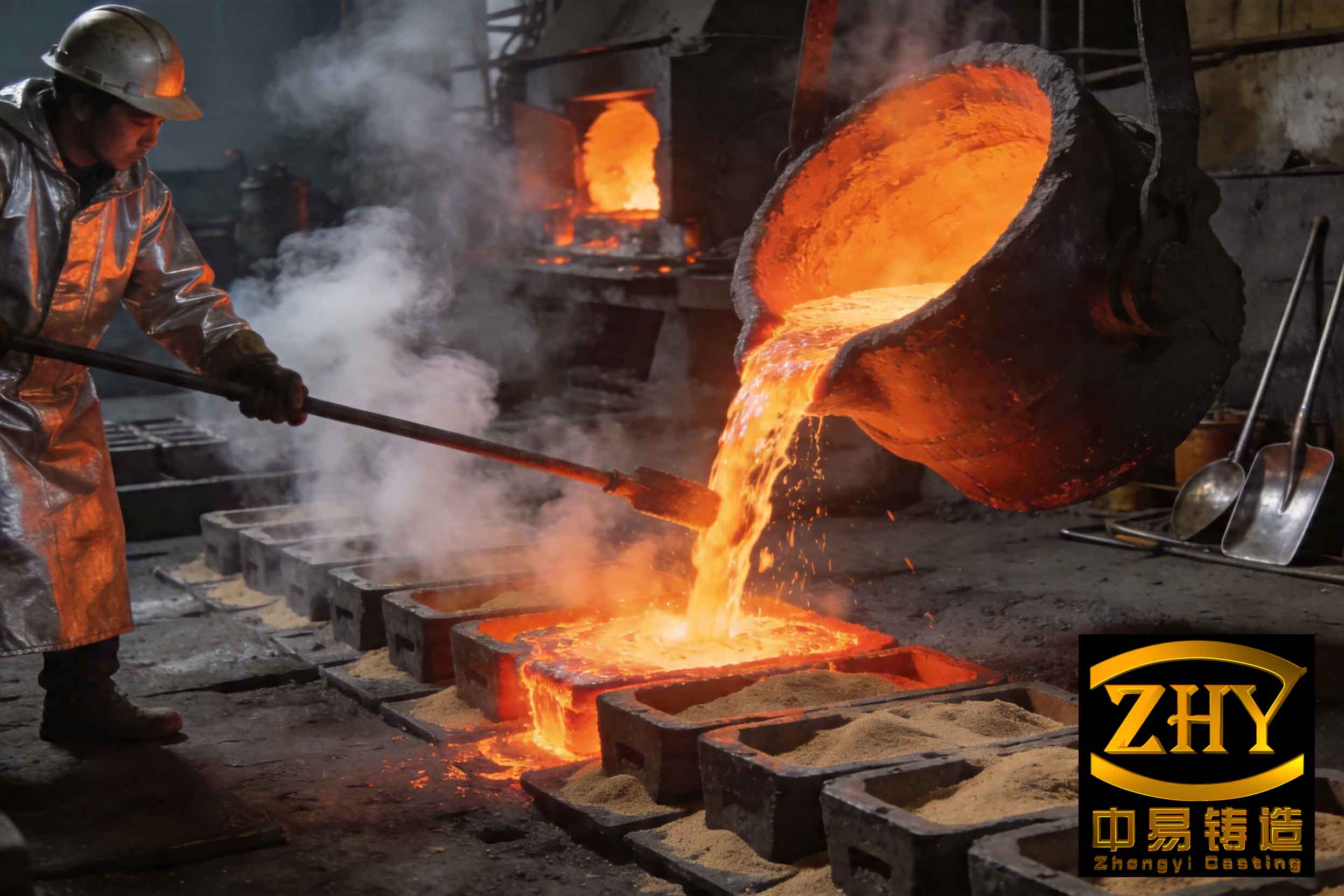
In my extensive experience in foundry engineering, slag inclusion defects remain one of the most persistent and detrimental issues in the production of ductile iron castings. These defects, often manifesting as black spots or slag inclusions, not only compromise the mechanical properties of castings but also lead to significant scrap rates, impacting both productivity and profitability. The term ‘slag inclusion’ refers to non-metallic impurities entrapped within the casting matrix, primarily composed of oxides and sulfides. Throughout this article, I will delve deep into the mechanisms of slag inclusion formation, analyze a specific case study, and present a detailed solution involving gating system modification and filter application. The keyword ‘slag inclusion’ will be emphasized repeatedly to underscore its criticality. To visually illustrate the severity of such defects, I include a representative image below.
The formation of slag inclusion is a multifaceted process influenced by melting, treatment, pouring, and molding practices. Fundamentally, slag inclusions can be categorized into two types: primary slag inclusions and secondary slag inclusions. Primary slag inclusions originate from oxides and sulfides generated during the spheroidization treatment that are not adequately removed before pouring. These tend to be located near the casting surface. Secondary slag inclusions, on the other hand, form inside the casting during the period between pouring and solidification, often resulting from re-oxidation and turbulent flow within the mold. They are typically finer and more dispersed. The chemical composition of slag inclusion is complex, involving elements such as Mg, Si, Al, Ca, and S, forming compounds like MgO, SiO₂, MgS, and others. The presence of slag inclusion severely reduces tensile strength, impact toughness, and pressure tightness, making its control paramount.
To quantify the impact, consider the mechanical property degradation due to slag inclusion. The effective stress in a casting containing a slag inclusion can be modeled using fracture mechanics principles. For instance, the stress intensity factor \( K_I \) for a crack-like slag inclusion is given by:
$$ K_I = \sigma \sqrt{\pi a} $$
where \( \sigma \) is the applied stress and \( a \) is the effective size of the slag inclusion. This leads to a reduction in the ultimate tensile strength \( \sigma_u \) as:
$$ \sigma_u = \frac{K_{IC}}{\sqrt{\pi a}} $$
Here, \( K_{IC} \) is the fracture toughness of the ductile iron. Larger slag inclusions significantly lower \( \sigma_u \), exemplifying why controlling slag inclusion size and distribution is crucial.
In our foundry, we encountered a severe slag inclusion problem in the production of an outer diffuser casting for a gas engine. This ductile iron casting, with a material grade of QT400-18, had a rough weight of 1480 kg and a total poured weight of 2000 kg. The pouring temperature was maintained between 1315°C and 1330°C, with a pouring time of 30 ± 5 seconds. Initially, the scrap rate due to slag inclusion reached up to 12%, with defects concentrated on the top surfaces and inner wall areas. Metallographic analysis of the top surface revealed large, dendritic slag inclusions exceeding 600 µm in length, characteristic of secondary oxidation slag inclusion. This indicated that the issue was related to turbulent flow during mold filling.
The original gating system was a pressurized system with a middle pouring design. The parameters were as follows: sprue diameter of 70 mm (cross-sectional area 38.465 cm²), two horizontal runners with dimensions 40/60 × 80 mm (total area 80.00 cm²), and eight ingates with dimensions 38/42 × 10 mm (total area 32.00 cm²). The ratio \( F_{\text{sprue}} : F_{\text{runner}} : F_{\text{ingate}} \) was 1 : 2.07 : 0.83. While such a system aids in feeding, it results in high metal velocity at the ingates. The ingate velocity \( v \) can be calculated using the continuity equation:
$$ v = \frac{Q}{A} $$
where \( Q \) is the volumetric flow rate and \( A \) is the total ingate area. Given the pouring time \( t = 30 \, \text{s} \) and poured weight \( W = 2000 \, \text{kg} \), the density of ductile iron \( \rho \approx 7000 \, \text{kg/m}^3 \), the flow rate is:
$$ Q = \frac{W}{\rho t} = \frac{2000}{7000 \times 30} \approx 0.00952 \, \text{m}^3/\text{s} $$
Converting ingate area to m²: \( A = 32.00 \, \text{cm}^2 = 0.0032 \, \text{m}^2 \). Thus,
$$ v = \frac{0.00952}{0.0032} \approx 2.98 \, \text{m/s} $$
This high velocity, coupled with a falling stream into the mold cavity, caused severe turbulence, air entrainment, and oxidation, leading to the formation of secondary slag inclusion. The entrapped oxide films were then carried into the casting, resulting in the observed defects.
To address this, we redesigned the gating system to an unpressurized (open) system with the addition of ceramic foam filters. The primary goals were to reduce ingate velocity and remove primary slag inclusions. The choke section in an open system is the sprue. Based on empirical rules and calculations, we determined the required choke area \( A_c \) using the formula:
$$ A_c = \frac{W}{k \rho t \sqrt{2gh}} $$
where \( k \) is a efficiency factor (typically 0.8 for ductile iron), \( g \) is gravity (9.81 m/s²), and \( h \) is the effective metallostatic head. For our casting, \( h \approx 0.5 \, \text{m} \). Plugging in values:
$$ A_c = \frac{2000}{0.8 \times 7000 \times 30 \times \sqrt{2 \times 9.81 \times 0.5}} \approx 0.0027 \, \text{m}^2 = 27 \, \text{cm}^2 $$
We selected a sprue diameter of 60 mm, giving an area of approximately 28.27 cm², which is close to the calculated value. The new gating system ratios were set to \( F_{\text{sprue}} : F_{\text{runner}} : F_{\text{ingate}} = 1 : 2.17 : 2.7 \). The detailed dimensions are summarized in Table 1.
| Component | Dimensions | Cross-Sectional Area (cm²) | Number | Total Area (cm²) |
|---|---|---|---|---|
| Sprue (Ceramic Tube) | Ø60 mm | 28.27 | 1 | 28.27 |
| Horizontal Runner | 35/100 × 90 mm (Trapezoidal) | 60.75 | 2 | 121.50 |
| Ingate | 80/90 × 15 mm (Flat) | 12.75 | 6 | 76.50 |
The ingate velocity was recalculated with the new area \( A_{\text{ingate}} = 0.00765 \, \text{m}^2 \):
$$ v_{\text{new}} = \frac{0.00952}{0.00765} \approx 1.24 \, \text{m/s} $$
This reduction from nearly 3 m/s to 1.24 m/s significantly minimized turbulence and secondary slag inclusion formation.
Furthermore, we incorporated ceramic foam filters to capture primary slag inclusions. The filters were placed at the junctions between the sprue and runners. Based on manufacturer recommendations, each filter with dimensions 120 × 120 × 20 mm can handle up to 400 kg of molten iron. For our 2000 kg pour, we used six filters, arranged symmetrically. The filtration efficiency for slag inclusion removal can be expressed as:
$$ \eta = 1 – \exp\left(-\frac{\alpha L}{d_p}\right) $$
where \( \eta \) is the removal efficiency, \( \alpha \) is a filter constant, \( L \) is filter thickness, and \( d_p \) is the slag inclusion particle size. For our 20 mm thick filters, \( \eta \) exceeds 90% for particles above 50 µm, effectively reducing primary slag inclusion.
The modified system was implemented, and over 100 castings were produced continuously. The scrap rate due to slag inclusion dropped to near zero. Metallographic analysis of the previously problematic top surfaces showed no significant slag inclusion, as seen in Table 2 comparing defect metrics before and after modification.
| Parameter | Original Gating System | Modified Gating System |
|---|---|---|
| Ingate Velocity (m/s) | ~2.98 | ~1.24 |
| Slag Inclusion Frequency (%) | 12 | <0.5 |
| Max Slag Inclusion Size (µm) | >600 | <50 |
| Scrap Rate Due to Slag Inclusion (%) | 12 | ~0 |
The improvement underscores the importance of gating design in controlling slag inclusion. The open system ensures laminar flow, while filters trap impurities. Additionally, we optimized other factors to mitigate slag inclusion. For instance, the pouring temperature was tightly controlled, as higher temperatures increase oxidation. The relationship between oxidation rate \( R \) and temperature \( T \) follows an Arrhenius equation:
$$ R = A \exp\left(-\frac{E_a}{RT}\right) $$
where \( A \) is a pre-exponential factor, \( E_a \) is activation energy, and \( R \) is the gas constant. Keeping \( T \) at the lower end of the range (1315°C) reduced oxide formation.
Moreover, we enhanced slag removal during treatment by using better covering fluxes and improved skimming practices. The composition of the flux was adjusted to have a basicity index \( B \) defined as:
$$ B = \frac{\% \text{CaO} + \% \text{MgO}}{\% \text{SiO}_2} $$
A \( B \) value of 1.5 to 2.0 proved effective in absorbing MgO and MgS, common constituents of slag inclusion.
To further elaborate on the mechanisms, the formation of secondary slag inclusion is driven by the Reynold’s number \( Re \) of the flow in the mold:
$$ Re = \frac{\rho v D}{\mu} $$
where \( D \) is hydraulic diameter and \( \mu \) is dynamic viscosity. For \( Re > 4000 \), flow becomes turbulent, promoting slag inclusion entrapment. Our original system had \( Re \approx 8500 \), while the modified system reduced it to \( Re \approx 3500 \), ensuring transitional flow and less oxidation.
In conclusion, tackling slag inclusion requires a holistic approach centered on gating system design. By switching to an open gating system and incorporating ceramic foam filters, we successfully eliminated slag inclusion defects in the diffuser casting. The key was reducing ingate velocity to below 1.5 m/s and filtering out primary inclusions. This solution has been applied to other castings with similar success, highlighting its robustness. Continuous monitoring and adjustment of parameters like pouring temperature and treatment practices are also essential to prevent slag inclusion. The economic impact has been substantial, reducing scrap costs by over 90% and improving customer satisfaction. Future work may involve computational fluid dynamics (CFD) simulations to further optimize gating designs for complex castings, ensuring minimal slag inclusion formation. Through this experience, I reaffirm that understanding and controlling fluid dynamics is critical in combating slag inclusion in ductile iron foundries.
To summarize the technical insights, I present a formula for estimating the required ingate area \( A_{\text{ingate}} \) to avoid slag inclusion:
$$ A_{\text{ingate}} = \frac{W}{\rho t v_{\text{max}}} $$
where \( v_{\text{max}} \) is the maximum allowable velocity to prevent turbulence, typically 1.0-1.5 m/s for ductile iron. Using \( v_{\text{max}} = 1.2 \, \text{m/s} \), we get:
$$ A_{\text{ingate}} = \frac{2000}{7000 \times 30 \times 1.2} \approx 0.00794 \, \text{m}^2 = 79.4 \, \text{cm}^2 $$
Our design provided 76.5 cm², which is close, validating the approach. This formula can be a quick tool for engineers to design gating systems that minimize slag inclusion.
In closing, slag inclusion remains a formidable challenge, but with systematic analysis and targeted modifications, it can be effectively controlled. The integration of filtration and open gating is a proven strategy, and I encourage its adoption in foundries facing similar slag inclusion issues. By sharing this first-person account, I hope to contribute to the broader knowledge base on eliminating slag inclusion and enhancing casting quality.