This paper focuses on the issues of scab and shrinkage cavity defects that occur during the production of ductile iron gear reducer housings through lost foam casting. By optimizing the gating system, changing from top gating to bottom gating effectively reduces the turbulence of molten iron during the pouring process, solving the scab problem on the surface of the gear reducer housing. Additionally, a new heat dissipation process is explored to address the shrinkage cavity defects in the hot spot area of the casting. The experimental results demonstrate that after changing the gating system to bottom gating, the surface scab defect of the casting is completely resolved, and the shrinkage cavity defect is also addressed. This process is simple and has a high process yield.
1. Introduction
Lost foam casting is a modern casting technology that offers advantages such as good surface quality, high dimensional accuracy, and high process yield. It has found wide application in the production of ductile iron parts. Gear reducer housings are crucial components in mechanical equipment, demanding high strength, toughness, wear resistance, and shock resistance. The material commonly used for gear reducer housings is QT450 – 10. Given the characteristics of the gear reducer housing and the production capacity of foundry equipment, the lost foam casting process is selected. However, during the production process, problems such as scab and shrinkage cavity defects frequently occur, which seriously affect the quality and performance of the gear reducer housing. Therefore, it is of great significance to study and solve these problems.
2. The Original Process of Ductile Iron Gear Reducer Housing
2.1 Process Parameters
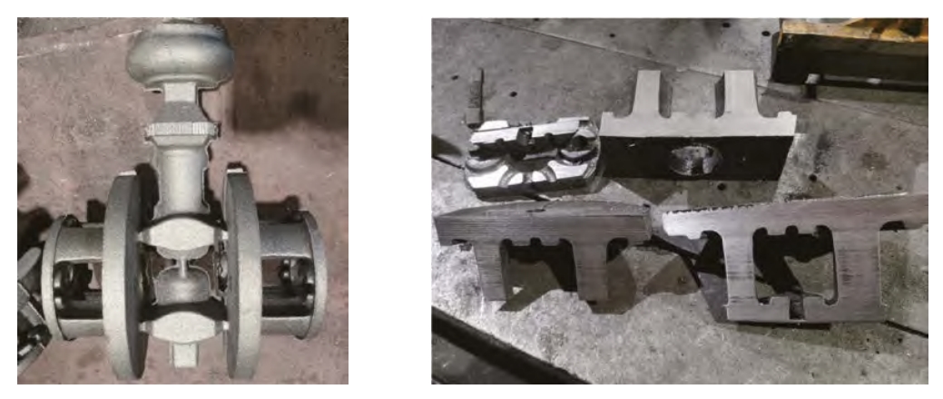
The combined process of the gear reducer housing is shown in Figure 1. The process allowance on the end face is designed to be 4 mm. The tapping temperature ranges from 1580 to 1600 °C, the pouring temperature is between 1370 and 1440 °C, the pouring negative pressure is -0.06 to -0.04 MPa, and the negative pressure holding time is 900 s. The chemical composition of the gear reducer housing is presented in Table 1.
| Figure 1: Gear Reducer Housing Combined Process | |||||||
|---|---|---|---|---|---|---|---|
| [Insert the actual figure of the combined process here] | |||||||
| Table 1: Chemical Composition of QT450 – 10 Gear Reducer Housing (Mass Fraction, %) | |||||||
| — | |||||||
| Main Elements | C | Si | Mn | P | S | Mg | RE |
| Content | 3.5 – 4.0 | 2.0 – 3.0 | ≤ 0.45 | ≤ 0.05 | ≤ 0.025 | 0.02 – 0.06 | 0.015 – 0.04 |
2.2 Defects in the Original Process
Although the mechanical properties of the Y – type specimen meet the requirements of QT450 – 10, and the nodularity of 2 – 3 levels also complies with the technical requirements of the ductile iron gear reducer housing, problems such as shrinkage porosity, shrinkage cavity, and scab defects occur during the trial production of the gear reducer housing by lost foam casting. During small – batch production, a large proportion of scab appears on the end face of the gear reducer housing, and shrinkage cavities are found at the geometric hot spots.
3. Formation Reasons of Scab and Shrinkage Cavity in Gear Reducer Housing
3.1 Formation Reasons of Scab
3.1.1 General Causes of Carbon – related Defects in Lost Foam Casting
Carbon – related defects are common in lost foam casting, and scab is a typical manifestation. After casting cleaning, scab appears as pits and bumps on the upper surface of the casting, resembling an orange peel. Scab defects often occur at the “cold end” of the liquid metal flow, such as the top, vertical side walls, or dead – end corners of the casting. During the thermal decomposition of the copolymer foam pattern used in lost foam casting, a large number of pyrolysis products in gaseous, liquid, and solid states are generated. The transfer process of these products is affected by multiple factors, resulting in diverse states, compositions, and discharge forms, which is the fundamental cause of diffuse carbon defects in lost foam casting.
3.1.2 Influence of the Original Gating System on Scab Formation
The original process of the gear reducer housing is structurally a top – gating system, but in fact, it is a mid – bottom gating process using the cavity as the runner. The casting is a rotating body with an upper – end thickness of 35 mm, and the thickness rapidly decreases to 13 mm below 50 mm. The original inner gate is designed on the top surface. During the pouring process, the high – temperature molten iron enters the top surface of the white mold from the inner gate. Instead of filling the mold gradually from top to bottom, the high – temperature molten iron directly penetrates the thick – walled area at the top, uses the top of the cavity as the runner, and starts to fill the mold in a fan – shaped manner downward when it reaches the thin – walled area. After reaching the bottom, it fills the mold upward. This actual mid – bottom gating turbulent filling method causes “cold end” areas in the thick and large dead – end areas at the top and sides, leading to scab defects.
3.2 Formation Reasons of Shrinkage Cavity
3.2.1 Analysis of Influencing Factors
Considering the carbon equivalent of ductile iron, since the mechanical properties of the Y – type specimen meet the requirements of QT450 – 10, the nodularity of 2 – 3 levels meets the technical requirements, and the chemical composition of the gear reducer housing is in line with the standards. Also, from the observation of the surface quality of the ductile iron gear reducer housing, there are no cold shuts or sand – adhering problems. Thus, factors such as spheroidizing treatment temperature, pouring temperature, and negative pressure on the shrinkage cavity of the gear reducer housing can be excluded.
3.2.2 Fundamental Cause
The fundamental cause of shrinkage cavity formation in ductile iron castings is that during the liquid shrinkage and solidification of the alloy, a certain part of the casting (usually the hot spot that solidifies last) cannot be timely compensated with liquid metal, resulting in irregularly shaped holes with rough walls at that location. For the gear reducer housing, the shrinkage cavity defects mainly exist in the thick – walled positions of the side – processed holes, which are mainly caused by geometric hot spots. To solve the shrinkage cavity problem of the gear reducer housing, it is necessary to start from the casting process measures, change the casting cooling structure, increase the heat dissipation surface area, reduce the local modulus, and eliminate the geometric hot spots of the casting.
4. Solutions and Verification for Gear Reducer Housing Defects
4.1 Solutions for Scab in Gear Reducer Housing
4.1.1 Redesign of the Gating System
The scab of the gear reducer housing is mainly due to the unreasonable design of the gating system, which leads to a mid – bottom gating filling method and causes turbulence of the molten iron during pouring, resulting in scab defects (Figure 3a). The solution is to redesign the gating system and change it to a bottom – gating system (Figure 2). In this way, the filling method becomes a pure bottom – gating method. During the filling process, the high – temperature molten iron fills the mold steadily from the bottom up, and finally, the low – temperature molten iron at the front end and the un – fully gasified products of the white mold stay at the processing allowance position on the top surface of the cavity, obtaining a sound – surfaced casting.
4.1.2 Calculation of the Gating System
The original process design of the gear reducer housing was unreasonable, resulting in a cumbersome bonding process, chaotic filling, and scab defects on the casting surface. The new casting process was redesigned, changing from top gating to central closed bottom gating and canceling the slag pocket on the upper end face. The theoretical calculation formulas for the gating system are as follows: The pouring time is calculated by the formula: \(t = 24S\) The height of the average static pressure head for bottom injection is calculated by the formula (\(P = C\)): \(H_{p}=H_{0}\), and \(H_{p}=34 cm\) The minimum cross – sectional area of the inner gate is calculated by the formula: \(A_{g}=\frac{G}{0.31 t v \sqrt{H_{p}}}=3.46 cm^{2}\) Theoretically, the minimum cross – sectional area of the inner gate is \(3.46 cm^{2}\). These calculation formulas are based on sand casting. According to production experience and the graphs of Rabinovich and Sai, the cross – sectional area of the inner gate can be obtained in the range of \((3.5 – 12) cm^{2}\). In the design of the lost foam casting gating system, the minimum cross – section of the inner gate is generally slightly larger than that of sand casting. According to the casting structure, the newly designed inner gate is a central casting, with four inner gates. The cross – sectional size of the inner gate is \((7 + 1×40)mm\), and the cross – sectional area of the inner gate is \((11.2 – 12.8) cm^{2}\). With a pressure head of 200 mm, the length of the straight gate is designed to be 480 mm.
4.1.3 Verification of the New Process
Based on the above – designed casting process, tests were carried out, and 2000 pieces were produced in batch for verification. The casting surface quality of the new casting process was qualified, and no batch – scale surface scab defects occurred again.
4.2 Solutions for Shrinkage Cavity Defects in Gear Reducer Housing
4.2.1 Inapplicability of Traditional Methods
For casting shrinkage cavity defects, there are two traditional solutions. One is to set risers at the hot spots to provide the metal liquid required for volume change during the casting formation process and eliminate shrinkage cavities. The other is to use a chilling system, and the most commonly used method is to use chills to make the hot spot area form an artificial end zone, which can turn the middle zone with almost no temperature difference into a chilled zone with a large temperature difference and form a sequential solidification to eliminate shrinkage cavity defects. However, for the lost foam casting of gear reducer housings, these two methods are not applicable. Adding risers reduces the process yield of the gear reducer housing casting and increases the overall process difficulty. In the process of using chills, due to the characteristics of lost foam casting, the chills are likely to fall off during molding and may cause casting deformation, resulting in high process difficulty, great impact on the quality stability of the gear reducer housing, and an increase in casting costs.
4.2.2 Development of the Heat Dissipation Process
A new lost foam casting process, the heat dissipation process, was developed to address the shrinkage cavity problem at the hot spots of ductile iron. The core objective of the heat dissipation process is to change the casting structure, increase the heat dissipation surface area, reduce the modulus at the hot spots of the casting, and allow the negative – pressure gas to take away a large amount of heat during the solidification stage, achieving a chilling effect. The specific method is to bond foam sheets (hereinafter referred to as heat dissipation sheets, as shown in Figure 4) at the hot spots of the casting. After that, the casting is produced through processes such as coating, drying, boxing, molding, and pouring. During the pouring and solidification process of the lost foam casting of iron, negative pressure is continuously applied. When the negative – pressure pump is working, cold air enters from the upper surface of the sand box, exchanges heat with the casting and the heat dissipation sheets, and takes away the heat. The heat dissipation sheets have a large specific surface area, which reduces the local modulus of the casting. The cold air takes away a large amount of heat, and a micro – channel flow heat transfer is formed between the local molding sand in contact with the casting and the heat dissipation sheets, creating a chilled zone with a large temperature difference. The heat dissipation sheets play the role of chills, making the local solidification mode of the casting similar to sequential solidification and eliminating shrinkage cavity and shrinkage porosity defects. The schematic diagram of the principle is shown in Figure 5.
4.2.3 Process Implementation and Verification
The gear reducer housing castings produced by the original process had shrinkage cavity defects in the bolt through – holes, as shown in Figure 6. By analyzing the casting structure, it was found that the shrinkage cavity position of the gear reducer housing belonged to a geometric hot spot, with a high tendency of shrinkage cavity, which was consistent with the shrinkage cavity defects in batch production. Considering various factors, the heat dissipation process was adopted. The specific process is shown in Figure 7. In the blanking and bonding process, 12 heat dissipation sheets with dimensions of \((50×30×7)mm\) were bonded in the hot – spot area of the casting. The other process steps remained unchanged. After trial production and machining verification, the bolt through – holes of the gear reducer housing were normal without quality problems (Figure 8). During batch production using the heat dissipation process, 2000 gear reducer housings were continuously produced, and no batch – scale shrinkage cavity defects occurred in the bolt through – holes after machining.
5. Conclusion
(1) By optimizing the gating system process, the filling process becomes stable, and the molten iron with impurities at the front end is collected using the process allowance, effectively solving the scab defect of the casting. (2) For the shrinkage cavity problem caused by hot spots in the lost foam casting of ductile iron parts, traditional riser and chill methods have high process difficulties. The newly designed heat dissipation sheet process can set a certain number of heat dissipation sheets at the hot spots of the casting. This can enhance the local heat dissipation speed, eliminate the geometric hot spots of the casting, and solve the shrinkage cavity defect of the casting. The heat dissipation sheet process has been verified by the gear reducer housing casting, proving that this process meets the design requirements and can solve the casting shrinkage cavity defect. It is a new method for solving shrinkage cavities in lost foam casting.
6. Future Research Directions
Although the methods proposed in this paper have effectively solved the scab and shrinkage cavity problems in the lost foam casting of gear reducer housings, there is still room for further research. Future research can focus on the following aspects: (1) Further optimize the design parameters of the heat dissipation sheet, such as its size, shape, and layout, to improve the heat dissipation effect and further enhance the quality of the casting. (2) Explore the application of new materials for heat dissipation sheets to find materials with better heat – transfer performance and lower cost, which can further reduce the production cost of castings. (3) Combine numerical simulation technology with experimental research to more accurately predict the occurrence of casting defects and optimize the casting process, improving the efficiency of process development.
7. Acknowledgments
The authors would like to express their gratitude to all those who have provided help and support during the research process. Special thanks go to the colleagues in the laboratory for their assistance in experimental operations and data analysis.