
Figure 1 shows the displacement and overall deformation distribution of sand casting frame after cooling, dropping and unpacking. As can be seen from Fig. 1a, in the length direction of the sand casting frame, the maximum displacement occurs at the beams at both ends of the sand casting frame, and the deformation displacement at the right end beam is greater than that at the left end beam, and the maximum deformation can reach 4.3cm. The shrinkage of sand castings is also large at the protruding position; Other parts in the length direction of the sand casting frame basically shrink evenly. In the middle of the cross beam of the sand casting frame, due to the displacement constraint, the displacement in all directions is 0. Figure 1b shows the displacement distribution in the height direction of sand casting. It can be seen that the shrinkage of other parts in the height direction of sand casting is basically evenly distributed except for the edge protrusion and edge.
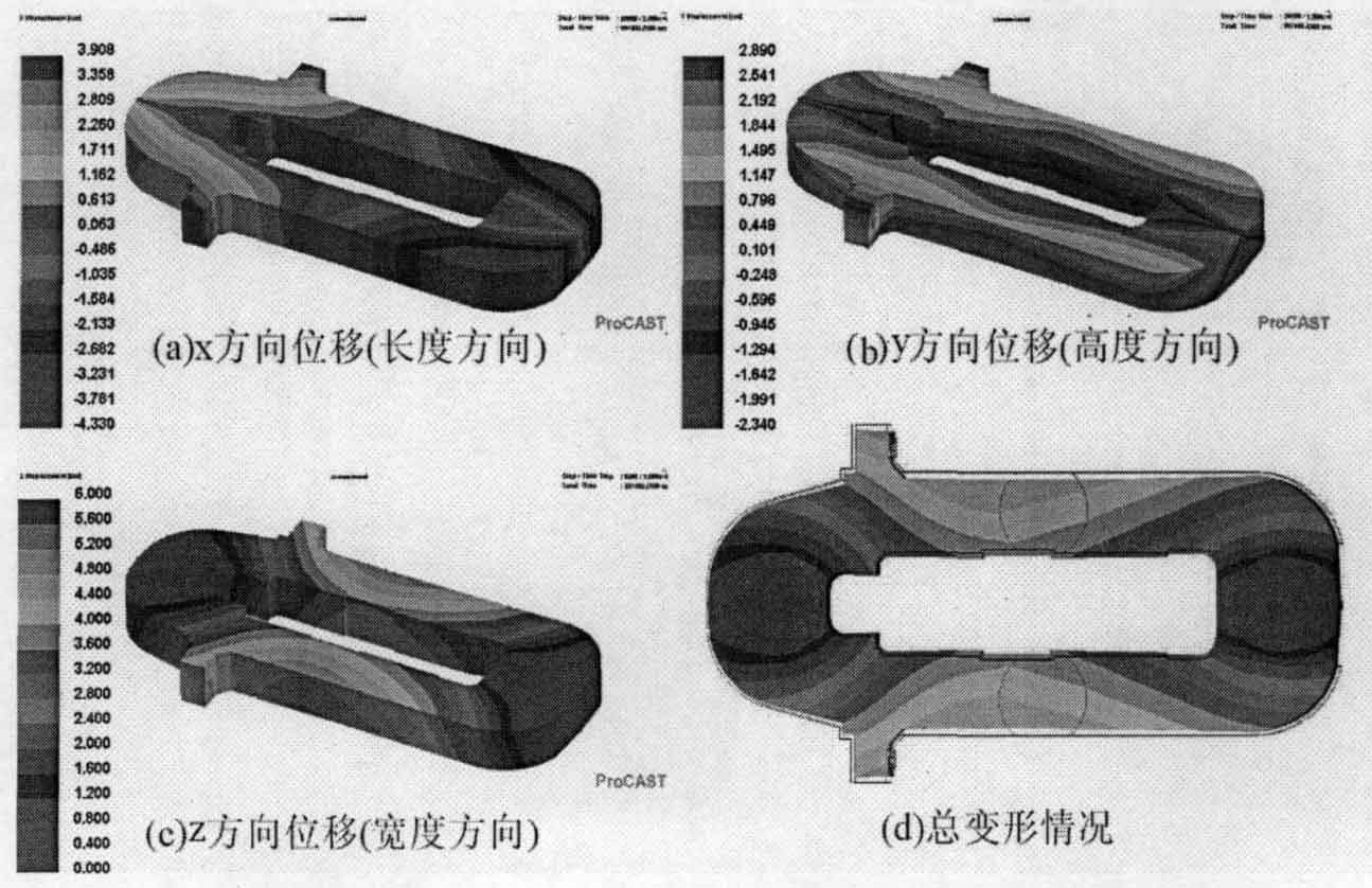
The displacement change in the width direction is shown in Figure 1C, from which it can be seen that the end beams on both sides are hindered by the mold due to solidification shrinkage, and the displacement change gradually decreases from the fillet of the inner wall to the symmetrical plane. The shrinkage is large in the middle of the column, and the shrinkage of the window of the column is also at a relatively high level. Figure 1D shows the overall deformation of the sand casting frame. It can be seen that the sand casting frame is basically in a uniform shrinkage state, the deformation is large at the bulge on the outside of the column and the middle of the column, and there is also obvious deformation outside the two end beams. At the window of the column, there is also a tendency to shrink inward due to the obstruction of the sand mold.
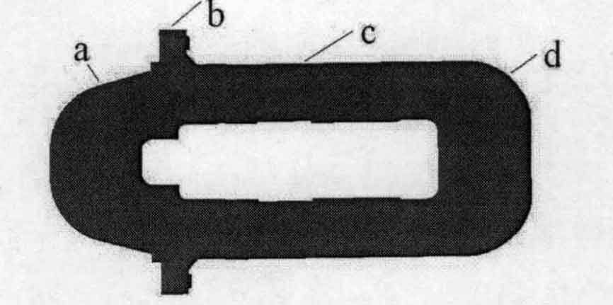
Four nodes are respectively taken at the maximum contour of the outer edge of the sand casting frame to facilitate the displacement analysis in the direction of the sand casting frame. The node position is shown in Fig. 2, and the displacement change diagram in X direction and Y direction is shown in Fig. 3 and Fig. 4.
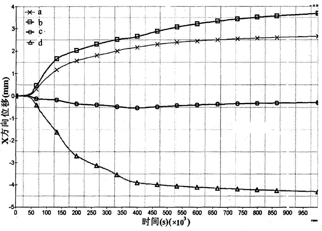
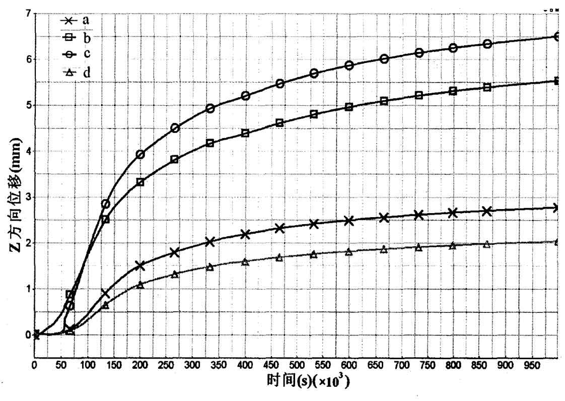
It can be seen from Fig. 3 and Fig. 4 that the deformation of sand casting has experienced two stages: the first stage is the stage of gradual increase of deformation, which is caused by the cooling shrinkage of the outer point of sand casting, but due to the release of crystallization latent heat, the temperature increases and the temperature difference decreases; The second stage is that the deformation of the outer point of the sand casting increases gradually under the influence of residual stress during the cooling process. In the X direction, the deformation of point a and point B is larger, and the deformation of point D is larger than that of point A. This is because the thickness of the beam at point D is larger than that of point a, which is close to 4.5mm; Compared with points a, B and D, point C is located in the middle of the column, and its deformation is obviously small, about 0.5cm. In the Z direction, the deformation of point C is significantly greater than that of the other three points, and the highest value is close to 6.5cm, which must be considered in the design. a. D due to the influence of the symmetry plane, the displacement value of the two points is relatively small, and the maximum value is about 2.5cm.